Welcome to The Circuit Board – a knowledge hub dedicated to VLSI, semiconductors, and electronics. Our mission is to simplify complex concepts and share clear, engaging insights into the world of electronics engineering. From foundational principles to the latest industry trends, we cover a wide spectrum of topics to help learners, professionals, and enthusiasts stay informed.
January 6, 2023
Step-by-step guide on how to interface load cell using Arduino.
Load cells are basically used to measure the weight of an object or a body. We can find these load cells in weighing machines, industry scales and several testing machines.
Definition: A Load Cell is a transducer that converts force such as pressure, torque, compression, or tension into measurable electrical output.
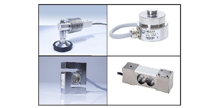
Some common types of load cells are Strain Gauges, Pneumatic Load cells, Hydraulic load cells, etc.
Types of Load Cell
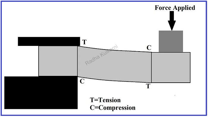
Strain gauge load cells are often found in industrial equipment. Load cells have strain gauges placed inside them. The body of these load cells is made up of aluminum, alloy steel, or stainless steel which makes it sturdy but also minimally elastic. When force is applied on one end of the load cell, the spring element present inside the load cell gets slightly deformed and changes its shape. It results in the alteration of resistance in the strain gauges which can be measured as voltage. Thus the change in voltage is proportional to the applied force which can be calculated from the load cells output. The working of the strain gauge load cell can be summarized in the below diagram.
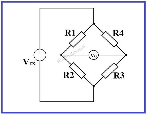
A single strain gauge can detect a small change in resistance hence it is difficult to measure the accurate changes. Increasing the number of strain gauges can magnify these small changes into a more measurable quantity. A set of 4 strain gauges placed in a particular fashion in a circuit is called a Wheatstone bridge. The below figure shows a Wheatstone Bridge for 4 balanced resistors.
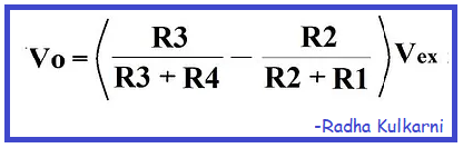
Here, Vex is the constant excitation voltage and Vo is the output voltage. R1, R2, R3, and R4 are 4 resistors placed in Wheatstone bridge formation. Here, if all resistors are balanced i.e., R1/R2=R4/R3 then the output voltage will be zero. Now even if the resistance of one resistor changes the Vo will eventually change. This change in Vo can be calculated using Ohm’s law. Output Voltage Vo can be expressed as:
Output Equation
In load cells, these resistors are replaced with strain gauges and are arranged in alternating tension and compression formation.
Now, we will see how to make a digital weighing scale using the Arduino Development board.
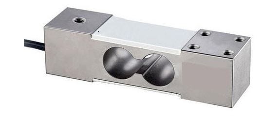
Components required: 1] Load cell: Here we will consider a simple Beam-type load cell as shown in the below figure.
Load Cell
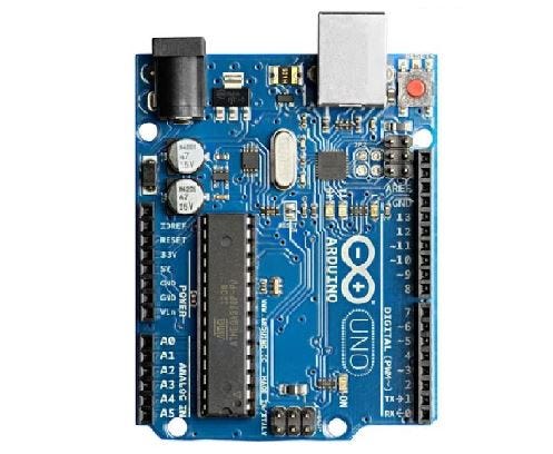
2] Arduino Uno Board: Arduino Uno Development board can be used for less complex operations such as weighing scale. We can select Arduino based on a number of I/O pins, input and output voltage, size, cost, etc.
Arduino UNO
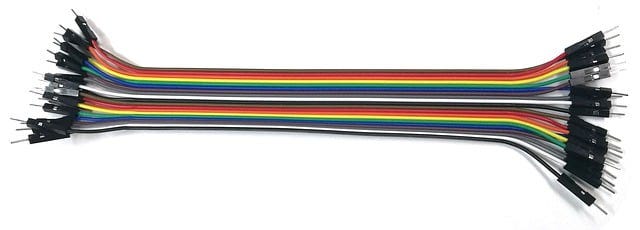
3] Jumper wires: Jumper wires are used to connect different points in a circuit. They are divided into 3 types: male-female, male-male, and female-female.
Jumper Wire
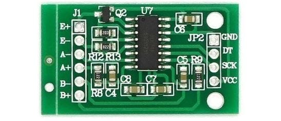
4] HX711 Interface Module: The output of the load cell is in the range of millivolts, hence we need to amplify this signal into a higher level signal and then transform it into a digital signal for processing. For this purpose, we use the HX711 interface module which will amplify the low voltage output of the load cell and send it to Arduino to calculate the weight. The below figure shows the HX711 interface module.
HX711
5] USB cable: It is used to establish the connection between the computer and the Arduino board.
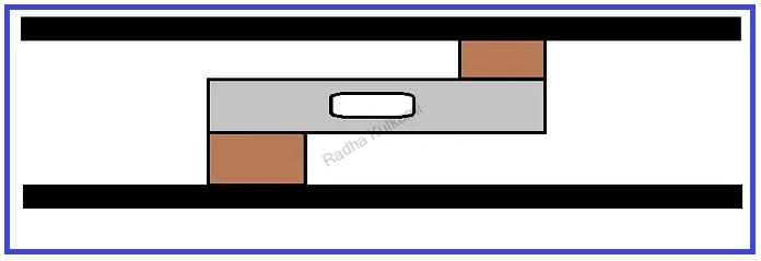
First, we will mount the load cell in a unique way between two fixed surfaces as shown in the below figure:
A load cell has 4 holes and a label that shows the direction of the force. The side without the label on it must be mounted to the fixed surface and the side with the label must be mounted to the moving surface. Place standoffs or washers between the mounting plates and load cells.
Connections:
Below figure shows circuit connections for interfacing load cells using Arduino:
2] Connect load cell to HX711 and HX711 to Arduino as shown in the above figure. Then connect the USB cable between Arduino and Computer.
3] Open Arduino Software and install HX711 libraries. 4] Calibrating the load cell is the most complex task in the complete operation. Here, I will share a simple method to calibrate the load cell which will work on every load cell and give the most precise and accurate output. 5] After downloading all the libraries, run the below code on Arduino Software:
#include “HX711.h” #include <Wire.h>
// HX711 circuit wiring const int LOADCELL_DOUT_PIN = 4; const int LOADCELL_SCK_PIN = 5;
if (scale.is_ready()) { long reading = (scale.read())*100; float grams = (float)(reading) / 100000 ; Serial.print(grams); } else { Serial.println(“HX711 not found.”); } delay(1000); }
Run the above code and open the console window from the top-right corner. Here, you will see random readings and as we place different weights on the load cell the readings will eventually change. Now, we write the reading and applied weights in the table as shown below:
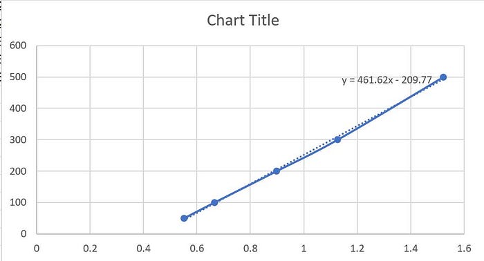
Here, I have used 5 different weights and received 5 different readings. We can increase the applied weights to get a more accurate output. Now add these readings to an Excel sheet and plot a linear graph as shown below:
By double clicking on the line on the graph, we will get the equation of the graph which we will add to the Code. Here, the equation is: y=461.62x-209.77
Now, make respective changes in the code as below:
#include “HX711.h” #include <Wire.h>
// HX711 circuit wiring const int LOADCELL_DOUT_PIN = 4; const int LOADCELL_SCK_PIN = 5;


No comments:
Post a Comment