Showing posts with label MOSFET. Show all posts

November 6, 2024

Explore Our Topics!

Check out the extensive list of topics we discuss: 

  1. Communication Protocols:
    USB 
    - RS232 
    Ethernet 
    AMBA Protocol: APB, AHB and ASB 
    UART, I2C AND SPI
  2. Important concepts in VLSI:
    Designing a Chip? Here Are the 12 Important Concepts You Need to Know
    Metastability 
    - Setup time and Hold time
    Signal Integrity and Crosstalk effect
    Skews and Slack 
    Antenna Effect
  3. Semiconductor Memories
  4. Most Frequently Asked Questions in VLSI
  5. Transistors:
    BJT
    JFET
    MOSFET
    CMOS
    Transmission Gate CMOS
    Dynamic CMOS
  6. Sequential Circuits:
    Registers
    Counters
    Latches
    Flip Flops
  7. FPGA:
    ASIC vs FPGA
    FPGA Insights: From Concept to Configuration
    Full-Custom and Semi-Custom VLSI Designs: Pros, Cons and differences
    From Theory to Practice: CMOS Logic Circuit Design Rules Made Easy with Examples
  8. CMOS Fabrication:
    CMOS Fabrication
    Twin-Tub CMOS Technology
  9. Combinational Circuits
    - Logic Gates 
    - Boolean Algebra and DeMorgan's Law 
    - Multiplexer (MUX) and Demultiplexer (DEMUX) 
    - Half Adder
    - Full Adder
    - Half Subtractor
    - Full Subtractor
    - Encoders
    - Decoder
  10. Analog Electronics
    - OPAMP
    - Inverting and Non-inverting Amplifiers
    - Characteristics of OPAMP
    - OPAMP Application: Adder, Subtractor, Differentiator, and More!  
    - Filters
  11. Verilog
    - Verilog Datatypes
    - Comments, Numeral Formats and Operators
    - Modules and Ports
    - assign, always and initial keywords
    Blocking and Non-Blocking Assignments
    - Conditional Statements
    - Looping Statements
    - break and continue Statement
    - Tasks and Functions
    - Parameter and generate
    - Verilog Codes
  12. System Verilog: 
    Disable fork and Wait fork.
    Fork and Join.
  13. Project on Intel Quartus Prime and Modelsim:
    Vending Machine Controller
  14. Xilinx Vivado Projects
    1)VHDL
    Counters using Testbench code
    Flip Flops using Testbench code
    Logic Gates using Testbench code
    Full Adder using Half Adder and Testbench code
    Half Adder using Testbench code
    2)Verilog
    Logic Gates using Testbench code
    Counters using Testbench code
    Full Adder using Half Adder and Testbench code
    Half Adder using Testbench code
  15. VLSI Design Flow:
    Design Flow in VLSI
    Y chart or Gajski Kuhn Chart
  16. Projects on esim:
    Step-by-Step guide on how to Design and Implement a Full Adder using CMOS and sky130nm PDK
    Step-by-Step guide on how to Design and Implement a Half Adder using CMOS and sky130nm PDK
    Step-by-Step guide on how to Design and Implement a 2:1 MUX using CMOS and sky130nm PDK
    Step-by-Step guide on how to Design and Implement a Mixed-Signal Circuit of 2:1 Multiplexer
  17. IoT based project:
    Arduino
    Step-by-Step guide on how to Interface Load Cell using Arduino
  18. Kmaps:
    Simplifying Boolean Equations with Karnaugh Maps - Part:2 Implicants, Prime Implicants and Essential Prime Implicants. 
    Simplifying Boolean Equations with Karnaugh Maps - Part:1 Grouping Rules.
    Simplifying Boolean Equation with Karnaugh Maps.

January 6, 2023

CMOS

  • CMOS technology, abbreviated for Complementary Metal-Oxide-Semiconductor, stands as a cornerstone in modern digital design, serving as the backbone for numerous electronic devices. This blog aims to explore the intricacies of CMOS technology, encompassing its fundamental principles, transistor structure, advantages, fabrication process, applications in VLSI design, and future prospects.
  • At the core of CMOS technology lies the utilization of both NMOS (N-channel Metal-Oxide-Semiconductor) and PMOS (P-channel Metal-Oxide-Semiconductor) transistors. Diverging from the traditional TTL (Transistor-Transistor Logic), CMOS distinguishes itself with its exceptional attributes, including low power consumption and remarkable noise immunity, rendering it a preferred choice for contemporary digital circuits.
  • By employing complementary pairs of p-type and n-type MOSFETs (Metal-Oxide-Semiconductor Field-Effect Transistors), CMOS technology enables symmetrical and efficient logic functions. This technology finds extensive use in crafting integrated circuit (IC) chips, ranging from microprocessors and microcontrollers to memory chips (including CMOS BIOS) and various digital logic circuits.
  • Structure and operation:
  1. In CMOS technology, the structure involves connecting the gate terminals of both NMOS and PMOS transistors together. The VDD (power supply voltage) is connected to the source of the PMOS transistor, while GND (ground) is connected to the source of the NMOS transistor.
  2. Additionally, the drain terminals of both NMOS and PMOS transistors are connected together, and the output is connected to this common drain node.
  3. For the PMOS transistor:
    - When the input signal is 0, the source-to-drain terminal of the PMOS transistor acts as a closed or short circuit.
    - When the input signal is 1, the source-to-drain terminal of the PMOS transistor acts as an open circuit.
  4. For the NMOS transistor:
    - When the input signal is 1, the source-to-drain terminal of the NMOS transistor acts as a closed or short circuit.
    - When the input signal is 0, the source-to-drain terminal of the NMOS transistor acts as an open circuit.
  5. This arrangement allows CMOS circuits to implement complementary logic functions efficiently, where one type of transistor conducts while the other is off, resulting in low power consumption and high noise immunity.
  • Working:
  1. Input Signal = 0:
    - When the input signal is 0, the PMOS (P-channel Metal-Oxide-Semiconductor) transistor in the CMOS circuit acts as a short circuit (conducting).
    - At the same time, the NMOS (N-channel Metal-Oxide-Semiconductor) transistor acts as an open circuit (non-conducting).
    As a result, the output is pulled up to the supply voltage (VDD), typically representing a logic high or 1.
  2. Input Signal = 1:
    - Conversely, when the input signal is 1, the PMOS transistor in the CMOS circuit acts as an open circuit (non-conducting).
    - Meanwhile, the NMOS transistor acts as a short circuit (conducting).
    Consequently, the output is pulled down to ground (GND), typically representing a logic low or 0.
  • The below table summarizes the working of CMOS for ideal conditions.
  • Under ideal conditions, a CMOS circuit acts as an inverter (NOT gate). This is because the complementary behavior of the PMOS and NMOS transistors in a CMOS inverter ensures that the output is the logical complement of the input signal.
  • When the input is high (1), the output is low (0), and when the input is low (0), the output is high (1). This inversion behavior makes CMOS inverters fundamental building blocks in digital circuit design, allowing for logical operations and signal processing.
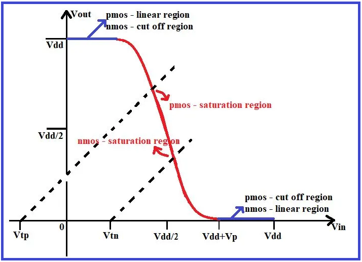
  • Voltage transfer characteristics to CMOS inverter.
  1. Threshold Voltages:
    Vtn​: Threshold voltage for NMOS transistor (positive value).
    - ∣Vtp​∣: Threshold voltage for PMOS transistor (absolute value, since it's negative).
  2. Voltage Definitions:
    Vgsn​: Voltage between the gate and source of NMOS.
    Vdsn​: Voltage between the drain and source of NMOS.
    Vgsp​: Voltage between the gate and source of PMOS.
    Vdsp​: Voltage between the drain and source of PMOS. Vdd​: Supply voltage.
  3. Conditions for Operation:

NMOS Transistor:

  • When Vgsn​<Vtn​, the NMOS transistor is in the cutoff region (off state).
  • When Vgsn​>Vtn​:

If Vgsn​−Vtn​>Vdsn​, the NMOS transistor is in the linear region.
If Vgsn​−Vtn​<Vdsn​, the NMOS transistor is in the saturation region.

PMOS Transistor:

  • When ∣Vgsp​>∣Vtp​∣, the PMOS transistor is in the cutoff region (off state).
  • When ∣Vgsp​<∣Vtp​∣:

If Vgsp​−∣Vtp​∣<Vdsp​, the PMOS transistor is in the linear region.
If Vgsp​−∣Vtp​∣>Vdsp​, the PMOS transistor is in the saturation region.

4. Voltage Transfer Characteristics:

Input = 0 (Logic Low):

  • NMOS Transistor: Vgsn​<Vtn​, NMOS is off (cutoff region).
  • PMOS Transistor: ∣Vgsp​>∣Vtp​∣, PMOS is off (cutoff region).
  • Output = Vdd​ (Logic High).

Input = 1 (Logic High):

  • NMOS Transistor: Vgsn​>Vtn​, NMOS is on (linear/saturation region).
  • PMOS Transistor: ∣Vgsp​<∣Vtp​∣, PMOS is on (linear/saturation region).
  • Output = GND (Logic Low).

Below graph shows the Voltage Transfer characteristics of CMOS.

  • Advantages of CMOS Technology:

CMOS technology offers numerous advantages, including low power consumption due to negligible static current, high noise margins, and scalability to smaller process nodes. These advantages have made CMOS the dominant technology in digital design.

  • CMOS Process Technology:

The CMOS (Complementary Metal-Oxide-Semiconductor) fabrication process involves several key steps to create integrated circuits. It typically starts with a silicon wafer, which undergoes cleaning and oxidation to create a thin layer of silicon dioxide (SiO2) on its surface. Photolithography is then used to pattern the wafer with photoresist, allowing for the creation of transistor structures through processes like ion implantation and diffusion to create the n-type and p-type regions.

Next, thin layers of metal (often aluminum or copper) are deposited and patterned using techniques like sputtering and etching to create the metal interconnects that link transistors and other components. Dielectrics, such as silicon dioxide or silicon nitride, are deposited and etched to isolate and insulate different parts of the circuit.
Each step requires precision and control to ensure the desired electrical characteristics and performance of the CMOS integrated circuit.

  • CMOS Scaling and Moore’s Law:

CMOS scaling refers to the continuous reduction in the size of CMOS (Complementary Metal-Oxide-Semiconductor) transistors and the overall components of integrated circuits. This scaling is a fundamental aspect of semiconductor technology advancement and is driven by the desire to increase the performance, density, and efficiency of electronic devices.

As transistors and other components are scaled down, their dimensions shrink, leading to several benefits such as higher integration density (more components in a smaller area), reduced power consumption, faster operation speeds, and lower manufacturing costs per unit. CMOS scaling has been a driving force behind the miniaturization of electronic devices and the development of increasingly complex integrated circuits.

Moore’s Law, formulated by Gordon Moore, states that the number of transistors on a microchip doubles approximately every two years, leading to a doubling of computing power and performance. This observation has been a guiding principle in the semiconductor industry and has driven continuous innovation and improvement in semiconductor technology.

  • Applications of CMOS in VLSI Design:

CMOS technology finds extensive use in VLSI design, powering microprocessors, memory chips, ASICs, and FPGA devices. Its low power consumption and high integration density make it ideal for designing complex digital systems.

In conclusion, CMOS technology stands as a pivotal force in modern digital design, offering a multitude of advantages such as low power consumption, high noise immunity, and scalability. Its fundamental principles, including complementary transistor behavior and efficient logic functions, make it a preferred choice for a wide range of applications in VLSI design, from microprocessors to memory chips and beyond. The CMOS fabrication process, with its precise steps and control, enables the creation of highly integrated circuits with exceptional performance and efficiency. As CMOS scaling continues to drive technological advancement, in tandem with Moore’s Law, the future of semiconductor technology remains promising, paving the way for even more sophisticated and powerful electronic devices.

Like, Share and Follow me if you like my content.
Thank You!

MOSFET

 Full Form: Metal Oxide Semiconductor Field Effect Transistor.

- It is a 4 terminal device: Gate, Source, Drain, and Substrate.
- Based on channel MOSFET can be divided into 2 types:
1] Enhancement Type MOSFET
2] Depletion Type MOSFET

- These types can be further divided as, n channel and p channel MOSFET:

  • Structure of Enhancement type MOSFET:

The above diagram shows an n channel Enhancement type MOSFET where the channel is made of n-type material, the substrate is made of p-type material and a SiO2 layer is mounted on it. To form the source and drain terminal we diffuse n+ type material on the p-type substrate. The region between source and drain is called a channel. Through metallic contacts, the drain and source terminals are connected to this n-type channel. Here, the gate terminal is also connected through metallic contact but is isolated from the channel using insulating material (SiO2). Due to this insulating material, no current will flow through the gate terminal and hence the gate terminal will have very high input impedance. It is called an Enhancement type MOSFET because by applying control voltage between Gate and Source, the channel is formed between Drain and Source hence, enhancing the number of charge carriers in the channel region.

  • Working:

    Case-1: Consider, that the gate and source terminal is connected to the ground i.e., Vgs=0V, and a positive voltage is applied between drain and source. As there is no channel present there will be no flow of current between source and drain. Therefore, when Vgs is zero, MOSFET will be in OFF condition, or it will be in the cut-off region.

Case-2: Now, we apply a voltage between gate and source and keep the voltage between drain and source (Vds) as 0V. Here, holes are the majority charge carriers in the p-type substrate, and hence when we apply positive voltage at the gate terminal holes near the oxide layer will get pushed away from the gate terminal, and electrons which are minority charge carriers from the p-type substrate will get attracted towards the oxide layer. But at a lower value of Vgs voltage, these electrons will get combined with these holes.

As we increase the gate voltage more holes will be pushed away from the gate terminal and electrons will overcome the recombination with these holes and get attracted towards the gate terminal and get accumulated at the insulating oxide layer and will form an inversion layer of free electrons near the oxide layer. This inversion layer will act as a channel with a drain and source region. Now, if we apply a voltage between drain and source (Vds) current will flow through this channel. The value of Vgs voltage at which the inversion layer is formed is called Threshold Voltage (Vth). Below this threshold voltage, there will be no flow of current through the channel. As we increase the Vgs voltage above Vth the channel width will go on increasing.

Along with the channel, there will also be a depletion layer between the n-type drain and source and p-type substrate region. These 2 PN junctions are reverse biased. Now, consider that Vgs>Vth and a positive voltage is applied between drain and source. Here, electrons will get attracted towards the positive terminal and current will flow through the circuit. The conventional current will flow from drain to source.

But as you can observe in the above figure that the width of the channel will get reduced at the drain terminal because due to positive voltage at the drain side the PN junction at the drain will get more reverse biased and the width of the depletion region will increase. Due to this, the effective channel width will decrease towards the drain terminal. As we increase this Vds voltage further Pinch OFF condition will occur where drain current will get saturated. So, the Vds voltage at which the Pinch OFF condition occurs is called Saturation voltage. This saturation voltage can be expressed as

Vds(sat) = Vgs-Vth

Case-3: If the keep Vgs constant and further increase Vds above Vds(sat) no channel will be formed at the Drain terminal. Here, it can be observed that no current flows through the channel but still electrons will pass towards the drain from the source due to electric force. So once the pinch-off condition occurs current Id gets saturated and if we increase Vds further current Id will remain constant.

  • The below graph shows the Drain characteristics of Enhancement type MOSFET:

For different values of Vgs, the graph of Id vs Vds will be as follows:
- As the value of Vgs increases the value of Id also increases.
- The parabolic curve shows the locus of Vds when the drain current Id will get saturated.
- The graph can be divided into 3 sections:
1] Linear or ohmic region: In this region, MOSFET can be operated as voltage controlled resistor. With the fixed value of Vds if we change the value of Vgs the width of the channel will change, or channel resistance will change. MOSFET will operate in this region when
Vds<Vgs-Vth,
Vgs>Vth


2] Cut-off region: When Vgs<Vth MOSFET will operate in this region. Here, no current will flow through the MOSFET, and MOSFET will be in an OFF state.

3] Saturation Region: When VdsVgs-Vth then MOSFET will operate in the saturation region.

  • The below graph shows the Transfer characteristics of Enhancement type MOSFET.

This graph shows the relation between input voltage Vgs and output drain current Id with a constant value of Vds.

- Here, we can see that till Vgs voltage is not equal to Vth, Id current will be zero and after Vgs=Vth as we increase Vgs voltage the Id current will also increase. The relation between Vgs and Id can be given as

Id=K(Vgs-Vth)2

Here, the value of k depends on the physical parameters of the device.

In this way, the MOSFET will function with respect to changes in different voltages.

Like, Share and Follow me if you like my content.
Thank You.

Explore Our Topics!

Check out the extensive list of topics we discuss:  Communication Protocols: -  USB   - RS232   -  Ethernet   -  AMBA Protocol: APB, AHB and...