- Counters are the sequential circuits which are used to count the pulses. It has input clock signal and group of output signals which display the count value.
- Upon each defined clock edge, it will either increment or decrement the count value. Flip flops are used as memory element. For an N bit counter, the maximum count will be 2^n.
- So if we have 3 bit counter then it will count till value 8. It can be also used as a frequency divider.
- They find applications in various fields such as digital signal processing, frequency division, and general counting tasks in digital systems.
- Based on the input clock signal counters can also be divided as follows:
- Synchronous: In synchronous counters, all flip flops share a common clock and change their state simultaneously. The changes in the state occur on the rising or falling edge of the clock.
- Asynchronous: In Asynchronous counters, all flip flops have separate clock and change its state at different times. The clock signals for each flip flop may come from different sources.
- Based on the way of counting counters can be classified as follows:
- Up Counter: It will start counting from zero to maximum N value.
- Down Counter: It will start counting from maximum N value to zero value.
- Up Down Counter: It will act as Up or Down counter based on the select/enable input.
- Now let us consider each counter one by one:
1] Up Counter:
- An Up Counter is an sequential circuit that counts upwards from 0 to the maximum N value. It increments its count on each rising edge(or falling edge depending on the design) of the clock signal. The count sequence is 0,1,2,….,(2^n-1), where n is the number of bits in the counter. Here’s an example of a 3-bit Up Counter:
- So it will initially start at 000 and after the first clock pulse it will increment to 001, after the second clock pulse it will increment to 010 and eventually after the seventh clock pulse it will increment to 111. The counter then resets to 000 on the eighth clock pulse, continuing the clock.
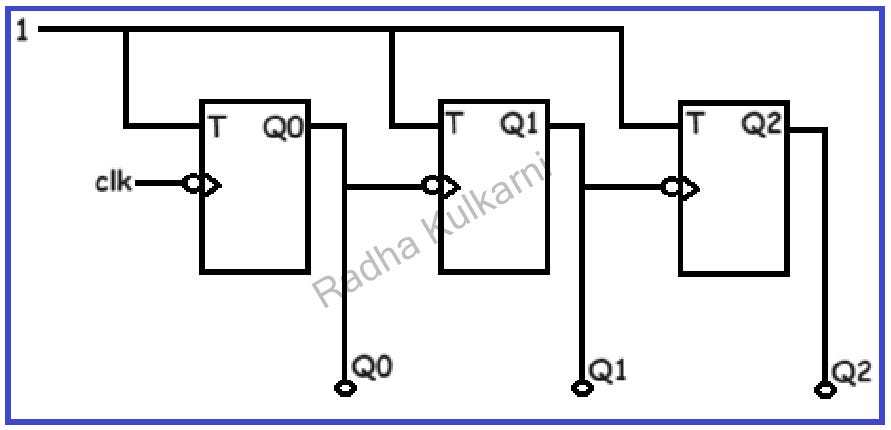
- Now, let’s examine the circuit and operation of a 3-bit up counter. For this, we require three memory elements, and we will be using T flip-flops as the memory elements. The diagram below illustrates the circuit for a 3-bit up counter using T flip-flops.

- Common inputs are provided to all flip-flops, and the input is set to ‘1’. Considering the behavior of T flip-flops, the output toggles when the clock is triggered. We have applied a negative-edge clock, and the output of the first flip-flop is connected to the input clock of the next flip-flop. Q0, Q1, and Q2 are the outputs, where Q0 is the least significant bit (LSB), and Q2 is the most significant bit (MSB).
- To comprehend the operation of the up counter, consider the output waveform below.

- Initially, assume all outputs are zero and plot the three outputs concerning the clock signal. According to the T flip-flop’s operation, the output Q0 toggles at every negative clock edge. For the next flip-flop, Q0’s output serves as the clock signal, toggling at every negative edge of Q0. Similarly, Q1’s output acts as the input clock for the subsequent flip-flop, and Q2’s output toggles with respect to the clock signal. Thus, we have Q0, Q1, and Q2 waveforms. By tracking the states of each output waveform, it becomes evident that the output states follow an increasing order from 0 to 7 (representing the 8 states of a 3-bit counter).
2] Down Counter:
- An Down Counter is an sequential circuit that counts downwards from its maximum value to 0. It decrements its count on each rising edge(or falling edge depending on the design) of the clock signal. The count sequence is (2^n-1),…,2,1,0, where n is the number of bits in the counter.
- Here’s an example of a 3-bit Down Counter:
- So it will initially start at 111 and after the first clock pulse it will increment to 110, after the second clock pulse it will increment to 101 and eventually after the seventh clock pulse it will increment to 000. The counter then resets to 111 on the eighth clock pulse, continuing the clock.
- Now, let’s examine the circuit and operation of a 3-bit down counter. For this, we require three memory elements, and we will be using T flip-flops as the memory elements. The diagram below illustrates the circuit for a 3-bit down counter using T flip-flops.

- Common inputs are provided to all flip-flops, and the input is set to ‘1’. Considering the behavior of T flip-flops, the output toggles when the clock is triggered. We have applied a negative-edge clock, and the output of the first flip-flop is connected to the input clock of the next flip-flop. The only difference in the operation of down counter is that here the output are Q0̅ , Q1̅ and Q2̅ rather than (Q0, Q1, and Q2), where Q0̅ is the least significant bit (LSB), and Q2̅ is the most significant bit (MSB).Consequently, the output waveforms are the exact opposites of those in the up counter, as they represent the complement outputs.
- To comprehend the operation of the Down counter, consider the output waveform below.

- Initially, assume all outputs are zero and plot the three outputs concerning the clock signal. According to the T flip-flop’s operation, the output Q0 toggles at every negative clock edge. For the next flip-flop, Q0’s output serves as the clock signal, toggling at every negative edge of Q0. Similarly, Q1’s output acts as the input clock for the subsequent flip-flop, and Q2’s output toggles with respect to the clock signal. Thus, we have Q0̅ , Q1̅ , and Q2̅ waveforms as the output. By tracking the states of each output waveform, it becomes evident that the output states follow an decreasing order from 7 to 0 (representing the 8 states of a 3-bit counter).
3] Up Down Counter:
- An Up-Down Counter is an sequential circuit that can be configured to act as either an Up Counter or a Down Counter based on a control input. It is also known as a bidirectional counter, is a type of counter that can count both upwards and downwards. It can be used to increment or decrement a count based on a control signal.
Here’s an example of 3 bit Up-Down counter: - Let us consider the counter is in the up counting mode:
So it will initially start at 000 and after the first clock pulse it will increment to 001, after the second clock pulse it will increment to 010 and eventually after the seventh clock pulse it will increment to 111. At this point, the counter reaches its maximum value and rolls over to zero. - Now lets consider the same counter in the down counting mode:
So it will initially start at 111 and after the first clock pulse it will increment to 110, after the second clock pulse it will increment to 101 and eventually after the seventh clock pulse it will increment to 000. The counter reaches its minimum value and rolls over to its maximum value. - The direction (up or down) is controlled by an external signal. When the control signal is set to “up,” the counter increments, and when it’s set to “down,” the counter decrements.
- We previously explored the use of an asynchronous counter for both up and down counting. Now, let’s delve into the workings of an Up-Down counter using a synchronous design.
- The steps outlined below illustrate how to design a Synchronous Up-Down Counter:
1] Identify the Number of Bits, Flip-Flops, and Type of Flip-Flops:
We will employ T flip-flops as memory elements, and for a 3-bit counter, three flip-flops are required, capable of counting up to ²³-1 = 7.
2] Write the Excitation Table of the Flip-Flop:
The excitation table for a T flip-flop is as follows:

3] Operation Based on Control Input M:
Consider the following:
If M = 0, the counter performs up counting.
If M = 1, the counter performs down counting.
4] Draw State Diagram and State Table:
The diagram below depicts the state diagram with eight states.

Based on the input M, states transition from state 0 to state 1 or from state 1 to state 0.
Now, let’s create a state table based on the state diagram. The table includes information about the present state, next state, and the inputs of the flip-flop.
Here, the T value is 1 if there is a change in the output state of a flip-flop (i.e., 0 to 1 and 1 to 0), otherwise 0.

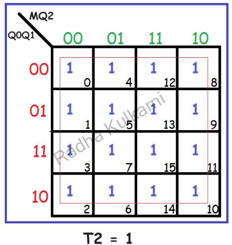
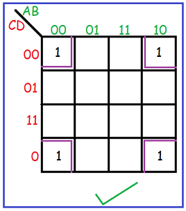
5] Find the Simplified Equations Using K-Maps:
Utilizing K-maps, we derive the equations for T0, T1, and T2.


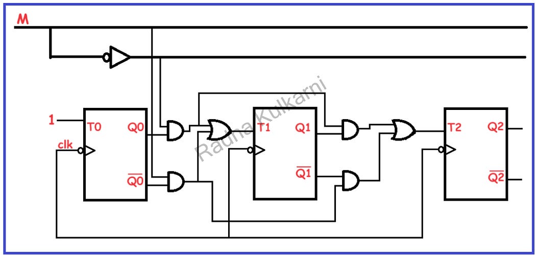
6] Create a Circuit Diagram:
The diagram below illustrates the circuit for a 3-bit synchronous Up-Down counter. All clock inputs are interconnected, and based on the boolean equations, the T inputs are connected.

7] Output Waveform Depending on the M Signal:
The diagram below showcases the output waveform based on the M signal.

This process outlines the design of a synchronous Up-Down counter.
To gain insights into the implementation of counters using VHDL and Verilog, please visit the link provided below.
1) VHDL
2) Verilog


