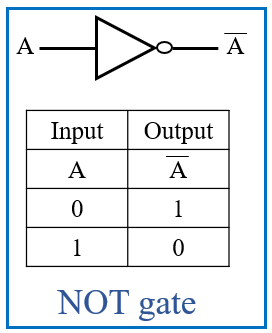
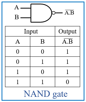
- In the world of digital electronics, where the magic of computation happens, lies a fundamental concept that serves as the building blocks for all operations: Boolean equations.
- These equations, rooted in the mathematics of Boolean algebra, govern the behavior of digital circuits, enabling the creation of complex systems from simple components. In this blog post, we’ll delve into the realm of Boolean equations.
- Boolean algebra deals with binary variables and logic operations. The variables take on the values of either 0 or 1, representing false and true, respectively. Boolean equations express logical relationships between these variables using operators such as AND, OR, and NOT.
- The basic operators in Boolean algebra are:
- AND (·): This operator returns true (1) only if both inputs are true.
- OR (+): This operator returns true (1) if at least one input is true.
- NOT (‘): This operator returns the opposite value of the input.
- Boolean Algebra operates under several fundamental laws that govern the manipulation and simplification of Boolean expressions. These laws provide a systematic way to analyze and optimize digital circuits. Let’s explore some of the key laws in Boolean algebra:
- Identity Laws:
1] Identity Law for OR: The OR operation with one operand being true always results in true.
A + 1 = 1
2] Identity Law for AND: The AND operation with one operand being false always results in false.
A · 0 = 0 - Domination Laws:
1] Domination Law for OR: If one operand of an OR operation is true, the result is true regardless of the other operand.
A + 0 = A
2] Domination Law for AND: If one operand of an AND operation is false, the result is false regardless of the other operand.
A · 1 = A - Idempotent Laws:
1] Idempotent Law for OR: ORing a variable with itself is the same as the variable itself.
A + A = A
2] Idempotent Law for AND: ANDing a variable with itself is the same as the variable itself.
A · A = A - Commutative Laws:
1] Commutative Law for OR: The order of operands in an OR operation does not affect the result.
A + B = B + A
2] Commutative Law for AND: The order of operands in an AND operation does not affect the result.
A · B = B · A - Associative Laws:
1] Associative Law for OR: The grouping of operands in an OR operation does not affect the result.
(A + B) + C = A + (B + C)
2] Associative Law for AND: The grouping of operands in an AND operation does not affect the result.
(A · B) · C = A · (B · C) - Distributive Laws:
1] Distributive Law for OR over AND: Distributing an OR operation over an AND operation.
A + (B · C) = (A + B) · (A + C)
2] Distributive Law for AND over OR: Distributing an AND operation over an OR operation.
A · (B + C) = (A · B) + (A · C) - Demorgans Laws
- A famous mathematician DeMorgan invented the two most important laws which play on important role in solving various boolean algebra expressions.
- It basically describes the amazing relationship between logic gates and their corresponding relations.
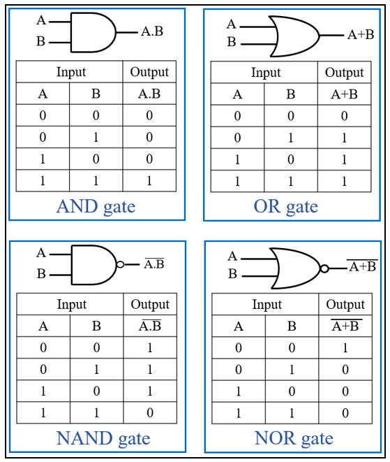
- These 2 laws deal with 4 logic gates: AND, OR, NOR and NAND.
- Let us consider each law one by one:
- But before we explore these laws, let’s refresh our memory with the truth tables of the AND, OR, NAND, and NOR gates:
1] Demorgan’s First Law:
According to the 1st Law, the complement of AND operation is equal to the OR operation of the complement of that variable. This can be summerized in the below figure and truth table.
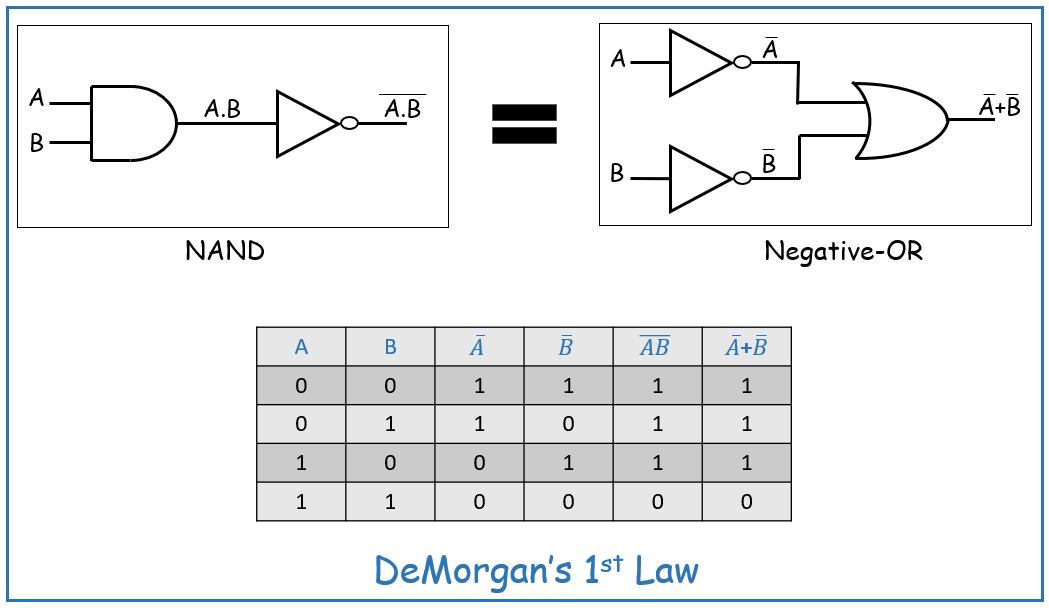
Here from the truth table you can observe that for each combination of values of A and B the output values of operation (A.B) bar and (A)bar + (B)bar are equal.
2] Demorgan’s Second Law:
According to the 2st Law, the complement of OR operation is equal to the AND operation of the complement of that variable. This can be summerized in the below figure and truth table.
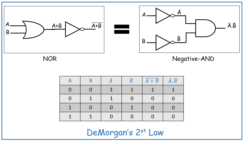
Here from the truth table you can observe that for each combination of values of A and B the output values of operation (A+B) bar and (A)bar . (B)bar are equal.
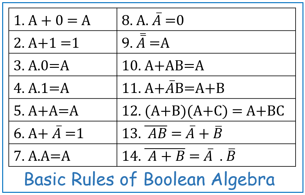
- Hence, below figure summerizes the rules of boolean algebra:
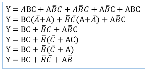
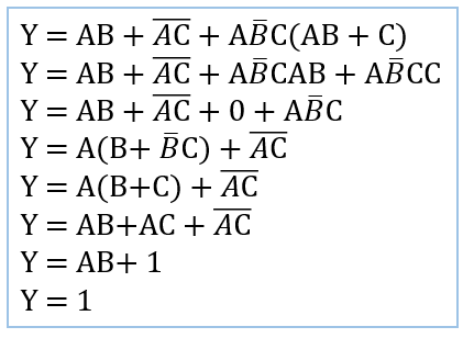
- Now let us consider few examples and see how these two laws help us evalute the output easily:
Example 1:
Example 2:
Boolean equations are the language of digital electronics, enabling engineers to design and analyze complex systems with precision and efficiency. By understanding the basic principles of Boolean algebra and mastering the manipulation of Boolean equations, one can unlock the full potential of digital circuitry. Whether you’re designing a basic logic gate or a sophisticated microprocessor, Boolean equations are your indispensable tool for success in the world of digital electronics.


