Showing posts with label CMOS. Show all posts

November 20, 2024

Explore Our Topics!

Check out the extensive list of topics we discuss: 

  1. Communication Protocols:
    USB 
    - RS232 
    Ethernet 
    AMBA Protocol: APB, AHB and ASB 
    UART, I2C AND SPI
  2. Important concepts in VLSI:
    Designing a Chip? Here Are the 12 Important Concepts You Need to Know
    Metastability 
    - Setup time and Hold time
    Signal Integrity and Crosstalk effect
    Skews and Slack 
    Antenna Effect
  3. Semiconductor Memories
  4. Most Frequently Asked Questions in VLSI
  5. Transistors:
    BJT
    JFET
    MOSFET
    CMOS
    Transmission Gate CMOS
    Dynamic CMOS
  6. Sequential Circuits:
    Registers
    Counters
    Latches
    Flip Flops
  7. FPGA:
    ASIC vs FPGA
    FPGA Insights: From Concept to Configuration
    Full-Custom and Semi-Custom VLSI Designs: Pros, Cons and differences
    From Theory to Practice: CMOS Logic Circuit Design Rules Made Easy with Examples
  8. CMOS Fabrication:
    CMOS Fabrication
    Twin-Tub CMOS Technology
  9. Combinational Circuits
    - Logic Gates 
    - Boolean Algebra and DeMorgan's Law 
    - Multiplexer (MUX) and Demultiplexer (DEMUX) 
    - Half Adder
    - Full Adder
    - Half Subtractor
    - Full Subtractor
    - Encoders
    - Decoder
  10. Analog Electronics
    - OPAMP
    - Inverting and Non-inverting Amplifiers
    - Characteristics of OPAMP
    - OPAMP Application: Adder, Subtractor, Differentiator, and More!  
    - Filters
  11. Verilog
    - Verilog Datatypes
    - Comments, Numeral Formats and Operators
    - Modules and Ports
    - assign, always and initial keywords
    Blocking and Non-Blocking Assignments
    - Conditional Statements
    - Looping Statements
    - break and continue Statement
    - Tasks and Functions
    - Parameter and generate
    - Verilog Codes
  12. System Verilog: 
    Disable fork and Wait fork.
    Fork and Join.
  13. Project on Intel Quartus Prime and Modelsim:
    Vending Machine Controller
  14. Xilinx Vivado Projects
    1)VHDL
    Counters using Testbench code
    Flip Flops using Testbench code
    Logic Gates using Testbench code
    Full Adder using Half Adder and Testbench code
    Half Adder using Testbench code
    2)Verilog
    Logic Gates using Testbench code
    Counters using Testbench code
    Full Adder using Half Adder and Testbench code
    Half Adder using Testbench code
  15. VLSI Design Flow:
    Design Flow in VLSI
    Y chart or Gajski Kuhn Chart
  16. Projects on esim:
    Step-by-Step guide on how to Design and Implement a Full Adder using CMOS and sky130nm PDK
    Step-by-Step guide on how to Design and Implement a Half Adder using CMOS and sky130nm PDK
    Step-by-Step guide on how to Design and Implement a 2:1 MUX using CMOS and sky130nm PDK
    Step-by-Step guide on how to Design and Implement a Mixed-Signal Circuit of 2:1 Multiplexer
  17. IoT based project:
    Arduino
    Step-by-Step guide on how to Interface Load Cell using Arduino
  18. Kmaps:
    Simplifying Boolean Equations with Karnaugh Maps - Part:2 Implicants, Prime Implicants and Essential Prime Implicants. 
    Simplifying Boolean Equations with Karnaugh Maps - Part:1 Grouping Rules.
    Simplifying Boolean Equation with Karnaugh Maps.

July 28, 2024

Explain the concept of latch-up in CMOS circuits and how it can be prevented.

Latch-up is a condition in CMOS circuits where a parasitic structure forms a low-impedance path between the power supply and ground, causing excessive current flow and potentially damaging the circuit. It can be prevented by using guard rings, proper layout techniques, and adding well-taps to control the substrate potential.

July 29, 2023

Simplifying Boolean Equations with Karnaugh Maps

 In this series, I will comprehensively cover all topics related to K Maps. The content will include the basic representation, rules for grouping, examples, and the Quine Mccluskey Minimization technique.

  • The Karnaugh Map, also known as the K Map, is a method used for simplifying Boolean expressions.
  • It was introduced by Maurice Karnaugh in 1953 and is built on the basis of Gray code, a binary numeral system in which two successive values differ in only one binary bit.
  • The process involves transferring the Boolean results from a truth table into a two-dimensional grid, where the cells are ordered in gray code, and each cell position represents a combination of input conditions.
  • The K-map can be used in two forms: Sum of Products (SOP) and Product of Sums (POS), depending on the problem’s requirements. For SOP, we place 1s at the respective cells, while for POS, we put 0s at the respective cells.
  • Let’s consider a 2-Variable Karnaugh Map (K-Map):
    To determine the total number of cells in the K-Map, we use the formula 2^n, where n is the number of variables. In this case, with 2 variables, we have 2² = 4 cells.
  • The diagram below illustrates a 2-variable K-Map with variables A and B, each capable of taking values 0 and 1. We can represent A as Abar when its value is 0, and as A when its value is 1, and similarly for variable B.
  • Each cell is identified by its corresponding row and column values. For instance, Cell 1 has the values A̅ and B̅ (00), so it is in the 0th position. Similarly, Cell 2 has the values A̅ and B (01), placing it in the 1st position. Cell 3 has the values A and B̅ (10), making it the 2nd position, and Cell 4 has the values A and B (11), making it the 3rd position. This method allows us to determine the positions of the cells accurately.
  • Now, let’s discuss using the K-Map to simplify a Boolean equation, for example, Y (A, B) = Σm(0, 3). To apply this equation to the K-Map, we place 1s at the 0th and 3rd positions. In this case the kmap will look as follows:

A minterm represents the most minimal expression of the mapped variables in a Boolean equation.

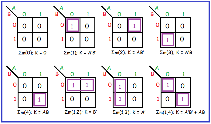
  • The following are all the possible 2- variable 2x2 Karnaugh maps:
  • Now, consider 3 variable K Map:
    The total number of cells for 3 variables will be 2³ which is 8 cells.
  • The below diagram shows the K Map for 3 variables.
    Here, for AB we will have 2-bit grey code combination sequence. Similar to 2 variable kmap 3 variable kmap will also have positions based on values of A, B and C.
  • Now, let’s discuss using the K-Map to simplify a Boolean equation, for example, Y (A, B, C) = Σm(0, 1, 4, 6). To apply this equation to the K-Map, we place 1s at the 0th, 1st, 4th and 6th positions. In this case the kmap will look as follows:
  • For the 4 variable kmap:
    The total number of cells for 4 variables will be 2⁴ which is 16 cells.
  • The below diagram shows the K Map for 4 variables.
    Here, for AB and CD we will have 2-bit grey code combination sequence. Similar to 2 variable kmap 4 variable kmap will also have positions based on values of A, B, C and D.
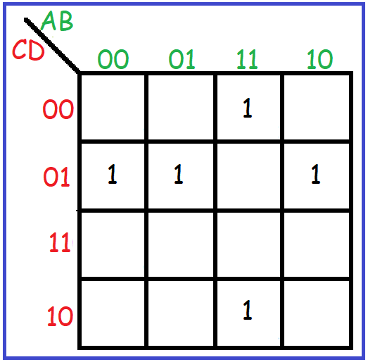
  • Now, let’s discuss using the K-Map to simplify a Boolean equation, for example, Y (A, B, C, D) = Σm(1, 5, 9, 12, 14). To apply this equation to the K-Map, we place 1s at the 1st, 5th, 9th, 12th and 14th positions. In this case the kmap will look as follows:

In my upcoming blog, I will delve into the topic of Rules for Grouping and Forming a Boolean Equation. Stay tuned for more! :)

Like, Share and Follow me if you like my content.
Thank You.

March 28, 2023

Dive deeper into the world of VLSI Design Methodologies

Welcome to our exploration of VLSI (Very Large Scale Integration) design methodologies. In the realm of VLSI, designers have two primary approaches: Full Custom Design and Semi-Custom Design. Each has its strengths and weaknesses, catering to different project requirements and constraints.

1] Full Custom Design: Full Custom Design involves creating and verifying all components of a chip from the transistor level upward. This meticulous process allows for precise optimization of speed, power, and area, making it ideal for mass production. However, it comes with a trade-off — the design and production time of full custom designs are typically longer compared to semi-custom designs.

  • Advantages of Full Custom Design:
  1. Optimized performance: Full custom designs can achieve higher performance levels compared to semi-custom designs.
  2. Area efficiency: By tailoring every component, full custom designs can minimize chip area.
  3. Power optimization: Fine-grained control over individual components enables power optimization.
  • Disadvantages of Full Custom Design:
  1. Longer design and production time: Designing and verifying each component from scratch can be time-consuming.
  2. Not cost-efficient for small-scale projects: The high upfront investment in design and fabrication makes full custom design less suitable for low-volume productions.

2] Semi Custom Design: Semi-Custom Design offers a compromise between design flexibility and time-to-market constraints. In this methodology, pre-designed and pre-tested modules are used, with the option to customize and add additional components as needed. While it reduces design time, it may not be as optimized or cost-efficient for mass production compared to full custom design.

  • Advantages of Semi-Custom Design:
  1. Reduced design time: Leveraging pre-designed modules accelerates the design process.
  2. Flexibility: Additional components can be integrated to meet specific requirements without starting from scratch.
  3. Suitable for low-volume productions: Semi-custom design offers a balance between customization and cost-effectiveness for smaller-scale projects.
  • Disadvantages of Semi-Custom Design:
  1. Limited optimization: Pre-designed modules may not offer the same level of performance optimization as full custom designs.
  2. Higher production time: Despite faster design time, integrating and customizing modules can extend the overall production time.
  • Performance analysis of design methodology w.r.t design time:
Performance Graph

From the above graph we can conclude following points:

  1. Initial circuit performance of the full custom design is less as compared to semi-custom design as we design it from the basic transistor level.
  2. Semi-custom has design less time compared to full custom design to get a stable circuit performance.
  3. Circuit performance of the full custom design is higher than the semi-custom design.
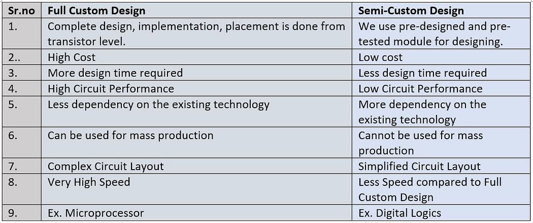
  • Comparison between Full Custom and Semi-Custom design:
Comparison between Full Custom and Semi-Custom Design
  • Classification of Semi-Custom Design:

1] Standard Cell Design:

Standard Cell
  • The above diagram shows standard cells semi-custom design.
  • Standard cells particularly use standard cell libraries which typically contain a few thousand cells, including inverters, Logic Gates, Adder circuits, Flip flops, AOI/OAI, etc.
  • Each gate in this library will have its driving capabilities and parameters based on which we decide which block to be used.
  • These standard cells have interconnects between them to perform different functions.
  • The masking cost of standard cells is high.
  • These cells can be used for both analog and digital designs.
  • We don't perform floorplanning in a standard cell as blocks are already placed.
  • Examples: Mux, Demux, Flip Flops, Logic Gates, Inverter, Adders, etc.

2] Gate Array Design:

Gate Array
  • The above diagram shows the structure of the Gate Array.
  • Here, the position of logic blocks is fixed.
  • These logic blocks can be connected using interconnection wires to perform different functions.
  • Structure also has I/O ports for interfacing.
  • Here we program wires and via to implement the desired functions.
  • In the gate array, the logic blocks are already placed in pre-defined positions but not connected to each other.
  • These gate arrays reduce making costs and also reduce design time.
  • As the size, no of logic blocks, transistors are fixed efficiency is less.

3] Programmable Logic Devices:

  • These are the IC that can be programmed according to the required specifications.
  • Some PLDs are :
    1] SPLD (Simple Programmable Logic Devices)
    2] CPLD (Complex Programmable Logic Devices)
    3] FPGA (Field Programmable Logic Devices)
  • Comparison between different Design styles:
Comparison between different Design styles

In conclusion, both full custom and semi-custom design methodologies play crucial roles in VLSI design. While full custom design offers unparalleled optimization and performance, semi-custom design provides flexibility and faster time-to-market for smaller-scale projects. Understanding the strengths and weaknesses of each approach is essential for selecting the most suitable methodology based on project requirements and constraints.

Like, Share and Follow me if you like my content.
Thank You.

Explore Our Topics!

Check out the extensive list of topics we discuss:  Communication Protocols: -  USB   - RS232   -  Ethernet   -  AMBA Protocol: APB, AHB and...