In digital electronics, an encoder is a crucial combinational circuit used to convert multiple input signals into a smaller, coded binary output. Encoders are widely used in digital systems for the efficient conversion of parallel inputs into serial binary codes, making them vital in devices like keyboards, control systems, and more.
What is an Encoder?
An encoder is a combinational circuit that converts multiple input signals into a coded output, typically in binary form. Encoders simplify complex data by reducing the number of signals needed to represent information. In essence, they perform the opposite function of decoders, which take a binary code and convert it into a specific output.

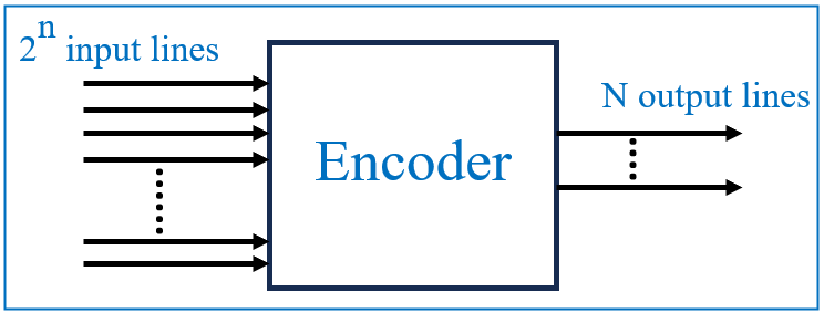
A basic encoder takes 2^n inputs and provides an n-bit binary output. This feature makes encoders extremely useful in applications where data reduction or compact representation is necessary.
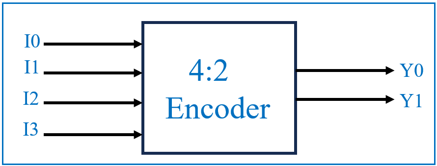
For example, a 4-to-2 encoder has four input lines (I0, I1, I2, I3) and two output lines (Y0, Y1). It takes the active input and converts it into a corresponding 2-bit binary code.
Types of Encoders
Encoders can be classified into different types based on their design and specific applications. Some of the most common types include:
- Binary Encoder: Converts 2^n input lines into n output lines, where each input is represented by a unique binary code. For example, a 4:2 encoder has four inputs and two outputs, encoding one active input into its binary equivalent.
- Priority Encoder: Adds functionality by assigning a priority to each input line. If more than one input is active at the same time, the encoder will prioritize the highest-order input and encode it. This type of encoder is useful when handling multiple simultaneous signals.
- Octal-to-Binary Encoder: Converts 8 input lines into a 3-bit binary output. It is typically used in systems where there are eight possible input states that need to be encoded into binary form for further processing.
- Decimal-to-BCD Encoder: Converts decimal input values into Binary-Coded Decimal (BCD). It’s widely used in calculators and other digital systems that need to display numbers as decimal digits, but process them as binary internally.
4:2 Encoder Explained
The 4:2 encoder consists of four inputs and two outputs. Only one input can be active at a time to generate the respective binary code at the output. The following truth table and logic diagram will illustrate the functionality.


This diagram represents a simple 4:2 encoder, which consists of four inputs (I0, I1, I2, and I3) and two outputs (Y0, Y1). The role of this encoder is to take one active input from the four inputs and convert it into a 2-bit binary output. The truth table provides a clear representation of the relationship between the inputs (I0, I1, I2, I3) and the outputs (Y0, Y1). The encoder works by mapping each input to a unique binary code based on the active input.
4:2 Encoder Logic Using OR Gates
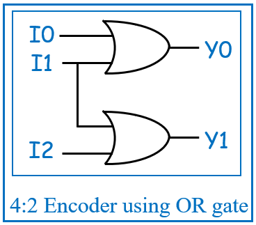
The logic diagram for a 4:2 encoder can be implemented using OR gates. In this diagram, the inputs are combined logically to produce the binary output. The Boolean equations that define the behavior of this encoder are:

- Y0 = I1 OR I3
- Y1 = I2 OR I3
These expressions show how the two OR gates combine the inputs to generate the respective outputs. If the inputs I1 or I3 are high, Y0 will be 1. Similarly, if I2 or I3 are high, Y1 will be 1. This ensures that the encoder produces the correct binary representation for each input.
Applications of Encoders
Encoders are widely used in various digital systems where data compression and signal reduction are needed. Some common applications include:
- Keyboards: Each key on a keyboard generates a unique binary code through an encoder, allowing the system to interpret the input efficiently.
- Control Systems: Encoders are used in control systems to encode signals for easy processing and transmission.
- Robotics: Encoders help track and control motion in robotic systems by encoding position or velocity data into a digital format.
- Multiplexers: Encoders are often used in multiplexing systems to select data channels for transmission.
Verilog Code for 4-to-2 Encoder
Here’s a simple Verilog code for a 4-to-2 binary encoder:
module encoder(y, v, i);
 input [3:0] i; // 4-bit input
 output reg [1:0] y; // 2-bit output
 output reg v; // Valid output
always @(*) begin
 case(i)
 4'd1: {v, y} = 3'b100; // Input 1 maps to output 00
 4'd2: {v, y} = 3'b101; // Input 2 maps to output 01
 4'd4: {v, y} = 3'b110; // Input 4 maps to output 10
 4'd8: {v, y} = 3'b111; // Input 8 maps to output 11
 4'd0, 4'd3, 4'd5, 4'd6, 4'd7, 4'd9, 4'd10, 4'd11, 4'd12, 4'd13, 4'd14, 4'd15: {v, y} = 3'b000; // All other cases
 default: $display("error"); // Display an error message for undefined cases
 endcase
 end
endmodule
Conclusion
Encoders are vital in digital electronics for converting multiple inputs into simplified binary outputs. Their ability to reduce data and prioritize signals makes them essential in many systems, including control systems, multiplexers, and more. Understanding how encoders work and how to implement them in hardware description languages like Verilog will strengthen your knowledge of digital circuit design.
No comments:
Post a Comment