Showing posts with label HDL. Show all posts

September 5, 2024

Mastering Verilog: Implementing a Barrel Shifter

Welcome to another edition of our Verilog series! In this blog post, we’ll explore the implementation of a Barrel Shifter in Verilog. A Barrel Shifter is a versatile digital circuit used for shifting data bits left or right by a specified number of positions. It’s a fundamental building block in many digital systems, particularly in arithmetic operations and data manipulation.

Below is the Verilog code for a Barrel Shifter, implemented using a Behavioral Modeling approach:

In the behavioral modeling approach, we describe the shifting functionality using simple conditional logic to decide between left and right shifts.

module barrel_shifter(
output reg [7:0] out, // Output shifted result
input [7:0] in, // Input data
input [2:0] n, // Number of positions to shift
input l_r // Shift direction (1 for left, 0 for right)
);
always @(*) begin
if (l_r) begin
// Left shift operation
out = in << n;
end else begin
// Right shift operation
out = in >> n;
end
end
endmodule

Explanation:

  • The always@(*) block ensures that the ‘out’ signal is updated whenever there is a change in the inputs ‘in’, ‘n’, or ‘l_r’.
  • If ‘l_r’ is high (‘1’), the input ‘in’ is shifted left by ‘n’ positions using the ‘<<’ operator.
  • If ‘l_r’ is low (‘0’), the input ‘in’ is shifted right by ‘n’ positions using the ‘>>’ operator.

Conclusion

This Verilog implementation of a Barrel Shifter demonstrates how to model a data-shifting circuit using behavioral constructs. Understanding how to design and implement a Barrel Shifter is essential for various applications in digital design, including arithmetic operations and data manipulation.

What’s Next?

Experiment with this Barrel Shifter design in your Verilog projects and explore how shifting data can be applied to solve different problems. In the next post, we’ll delve into more advanced digital circuit designs and their Verilog implementations.
Happy Coding!

Mastering Verilog: Implementing a Comparator

Welcome to another installment of our Verilog series! In this blog post, we’ll delve into the implementation of a Comparator in Verilog. Comparators are essential components in digital circuits, used to compare two values and determine their relationship — whether one is equal to, greater than, or smaller than the other.

Below are the Verilog codes for a 4-bit comparator using two different modeling styles: Dataflow and Behavioral.

1] Dataflow Modeling

In dataflow modeling, we describe the comparator functionality using continuous assignments.

module comparator (eq, gt, sm, a, b);
input [3:0] a, b;
output eq, gt, sm;
assign eq = (a == b); // Equality comparison
assign gt = (a > b); // Greater than comparison
assign sm = (a < b); // Smaller than comparison
endmodule

Explanation:

  • ‘assign eq = (a == b);’ checks if ‘a’ is equal to ‘b’.
  • ‘assign gt = (a > b);’ checks if ‘a’ is greater than ‘b’.
  • ‘assign sm = (a < b);’ checks if ‘a’ is smaller than ‘b’.

2] Behavioral Modeling

In behavioral modeling, we use an ‘always’ block to describe the comparator’s functionality.

module comparator_bh (eq, gt, sm, a, b);
input [3:0] a, b;
output reg eq, gt, sm;
always @(*) begin
eq = (a == b); // Equality comparison
gt = (a > b); // Greater than comparison
sm = (a < b); // Smaller than comparison
end
endmodule

Explanation:

  • The always@(*) block ensures that ‘eq’, ‘gt’, and ‘sm’ are updated whenever there is a change in ‘a’ or ‘b’.
  • The comparison operations are evaluated and assigned to the output variables accordingly.

Conclusion

These Verilog implementations demonstrate how to model a Comparator using different design approaches: dataflow and behavioral. Understanding these modeling styles will help you effectively compare values in your digital designs.

What’s Next?

Explore these comparator implementations in your Verilog projects and experiment with variations to enhance your understanding. In the next post, we’ll dive into more advanced digital components and their Verilog implementations.

Happy Coding!

September 4, 2024

Mastering Verilog: Implementing a 4:1 Multiplexer (MUX)

Welcome back to our Verilog series! In this blog post, we’ll explore the implementation of a 4:1 Multiplexer (MUX) in Verilog. A multiplexer is a crucial digital circuit used to select one of several input signals and route it to a single output line based on a control signal.

Understanding how to implement a 4:1 MUX is vital for designing complex digital systems.

Below are the Verilog codes for a 4:1 multiplexer using two different modeling styles: Dataflow and Behavioral.

1] Dataflow Modeling:

In dataflow modeling, we use the select signal to choose between one of the four inputs.

module mux(y, s, i);
input [3:0] i; // 4-bit input vector
input [1:0] s; // 2-bit select signal
output y; // Output
assign y = i[s]; // Select one of the 4 inputs based on s
endmodule

Explanation:
‘assign y = i[s];’ uses the select signal ‘s’ to index into the 4-bit input vector ‘i’, selecting one of its elements to be assigned to ‘y’.

2] Behavioral Modeling:

In behavioral modeling, we use a ‘case’ statement within an ‘always’ block to describe the multiplexer’s functionality.

module mux(y, s, i);
input [3:0] i; // 4-bit input vector
input [1:0] s; // 2-bit select signal
output reg y; // Output
always @(*) begin
case (s)
2'd0: y = i[0]; // If s is 00, output i[0]
2'd1: y = i[1]; // If s is 01, output i[1]
2'd2: y = i[2]; // If s is 10, output i[2]
2'd3: y = i[3]; // If s is 11, output i[3]
default: y = 1'b0; // Default case for safety
endcase
end
endmodule

Explanation:

  • The always@(*) block ensures that ‘y’ is updated whenever there is a change in ‘s’ or ‘i’.
  • The ‘case’ statement selects one of the four inputs based on the value of ‘s’.

Conclusion

These Verilog implementations showcase how to model a 4:1 Multiplexer using different design approaches: dataflow and behavioral. Understanding these modeling styles will help you design and implement multiplexers effectively in your digital circuits.

What’s Next?

Explore these MUX implementations in your Verilog projects and experiment with variations to deepen your understanding. In the next post, we’ll dive into more complex digital circuits and their Verilog implementations.

Happy Coding!

Mastering Verilog: Part 9 — Diving into Tasks and Functions

In our ongoing journey to master Verilog, we’ve explored various foundational concepts and advanced features. In this segment, we will focus on two crucial constructs in Verilog programming: Tasks and Functions. Understanding these constructs is essential for creating modular, reusable, and efficient Verilog code.

1. Introduction to Tasks and Functions

Tasks and functions in Verilog are used to encapsulate and reuse code. They help in organizing code into manageable pieces, making it more readable and maintainable. While both tasks and functions serve similar purposes, they have distinct characteristics and use cases.

Often, we encounter repetitive code segments in RTL (Register Transfer Level) that are invoked multiple times. These segments typically do not consume simulation time and often involve complex calculations with varying data values. In such instances, declaring a function to encapsulate the repetitive code can be highly beneficial. A function allows you to process inputs and return a single value, reducing the amount of RTL code you need to write. By calling the function and passing the necessary data for computation, you streamline your code and avoid redundancy.

In contrast, a task is more versatile. Tasks can handle multiple result values, returning them through output or inout arguments. They can include simulation time-consuming elements like ‘@’ or ‘posedge’. While functions do not consume simulation time and return only a single value, tasks may or may not consume simulation time and can return values via output or inout arguments.

Verilog Tasks

A task in Verilog is used to perform a sequence of statements and can include delays and timing control. Tasks are useful for operations that may require multiple statements and potentially involve waiting periods.

Syntax:

task task_name;
// Input and output declarations
input [width-1:0] input_name;
output [width-1:0] output_name;

// Task body
begin
// Task operations
end
endtask

Example:

module TaskExample;
reg [7:0] a, b;
reg [7:0] result;

// Task Definition
task add_two_numbers;
input [7:0] num1, num2;
output [7:0] sum;
begin
#5 sum = num1 + num2; // Perform addition with a delay
end
endtask

initial begin
a = 8'd10;
b = 8'd20;
add_two_numbers(a, b, result); // Call the task
$display(“The result of addition is: %d”, result);
$stop;
end
endmodule

Explanation:
Task Definition: ‘add_two_numbers’ takes two inputs (‘num1’ and ‘num2’) and provides an output (‘sum’), with a delay of 5 time units before computing the sum.
Task Call: The task is invoked in the ‘initial’ block to perform the addition.

Key Features of Tasks:
- Can contain delays and timing controls.
- Can have input, output, and inout arguments.
- Can call other tasks.
- May or may not consume simulation time, depending on their contents.

Verilog Functions

A function in Verilog is used for computing a value and returning it. Functions are typically used for simple calculations and must return a single value. They cannot contain delays or timing controls.

Syntax:

function [return_width-1:0] function_name;
input [input_width-1:0] input_name;
// Function body
begin
function_name = expression; // Compute and return value
end
endfunction

Example:

module FunctionExample;
reg [7:0] a, b;
reg [7:0] result;

// Function Definition
function [7:0] add_two_numbers;
input [7:0] num1, num2;
begin
add_two_numbers = num1 + num2; // Compute the sum
end
endfunction

initial begin
a = 8'd15;
b = 8'd25;
result = add_two_numbers(a, b); // Call the function
$display(“The result of addition is: %d”, result);
$stop;
end
endmodule

Explanation:
Function Definition: ‘add_two_numbers’ takes two inputs and returns their sum.
Function Call: The function is called in the ‘initial’ block to compute and return the result.

Key Features of Functions:
- Cannot contain delays or timing controls.
- Must return a single value.
- Cannot call tasks.
- Can be used within expressions.

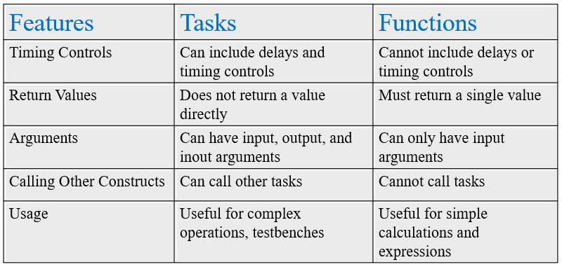
Differences Between Tasks and Functions

Practical Examples

  1. Task Example
    Suppose you are designing a complex digital system where you need to perform a sequence of operations with delays. A task can be used to encapsulate this logic and improve code readability.
  2. Function Example
    For simple calculations such as computing a checksum or performing bitwise operations, functions can be used within expressions to streamline your code.

Conclusion

Tasks and functions are powerful constructs in Verilog that enable modular, reusable, and efficient coding practices. Tasks are suited for complex operations with timing controls, while functions are ideal for simple computations. By encapsulating repetitive code segments in functions and leveraging tasks for more complex operations, you can enhance code maintainability and efficiency. Mastering these constructs will elevate your ability to design and verify digital systems effectively.

Stay tuned for more insights and advanced topics in our mastering Verilog series!

July 28, 2024

Explain the difference between behavioral and structural modeling in HDL.

Behavioral modeling in HDL describes the functionality of a digital system using high-level constructs without specifying the detailed implementation. It focuses on what the system does rather than how it is constructed. Structural modeling, on the other hand, describes the system in terms of its components and their interconnections, detailing the actual hardware implementation. Behavioral modeling is used for initial design and verification, while structural modeling provides a detailed and accurate representation for synthesis and implementation.

November 24, 2023

Mastering Verilog: Part 5 - Understanding Blocking and Non Blocking Statements


  • Procedural Statements in Verilog, such as blocking and non-blocking assignments, are categorized as elements of procedural blocks, such as ‘always’ and ‘initial.’
  • These statements play a crucial role in updating variables, and once a value is assigned, it remains unchanged until another procedural assignment modifies it. This stands in contrast to continuous assignments, where the value of a variable changes continuously.
  • In procedural assignments, the order of signal assignments and the flow of execution are explicitly determined, providing control over the sequencing of operations within the design.
  • Procedural blocks in Verilog primarily fall into two categories:
  1. always Blocks:
    Usage:
     Utilized to describe both combinational and sequential logics, triggered by events such as a clock edge (posedge or negedge).
    Example:
    always @(posedge clk) begin
    // Sequential or combinational logic here
    end
  2. initial Blocks:
    Usage:
     Employed to specify initial conditions or setup during simulation, executing once at the beginning.
    Example:
    initial begin
    // Initialization logic here
    end
  • Now let us see how these procedural statements work.

1] Blocking assignments:

  • Syntax:
    Specified using the ‘=’ operator.
  • Execution Flow:
    Statements are executed sequentially in the order specified within the procedural block.
    The execution of subsequent statements is blocked until the current assignment is completed.
  • Scope:
    Blocking assignments within one procedural block do not impact the execution of statements in other procedural blocks.
  • Example:
    Now let us consider below example to understand how blocking statements work. Below is not the complete verilog code but a module to understand the concept.

integer x,y,z;
initial
begin
x = 20;
y = 15;
z = 30;

x = y + z;
y = x + 10;
z = x — y;
end

Now the output for above logic will be as follows:

initially, x=20,y=15,z=30
x becomes 45
y becomes 55
z becomes -10

  • Initial Values:
    Initially, the values of x, y, and z are set to 20, 15, and 30, respectively.
  • Execution Steps:
    After the execution of the first statement (x = y + z), the value of x becomes 45.
    The second statement (y = x + 10) utilizes the updated value of x (now 45), resulting in y becoming 55.
    Finally, the third statement (z = x — y) uses the updated values of x (45) and y (55), causing z to become -10.

Provided below is the Verilog code for the logic mentioned above. Experiment with its implementation in simulation software to observe the output.

module blocking_assignment;
reg [31:0] x, y, z;

initial begin
x = 20;
y = 15;
z = 30;

// Blocking assignments
x = y + z; // x is assigned the value of y + z (15 + 30 = 45)
y = x + 10; // y is assigned the value of x + 10 (45 + 10 = 55)
z = x — y; // z is assigned the value of x — y (45–55 = -10)

// Displaying the values after the assignments
$display(“x = %0d, y = %0d, z = %0d”, x, y, z);
end
endmodule

  • Now let us consider the same example but with delays:

integer x,y,z;
initial
begin
x = 20;
y = 15;
z = 30;

x = y + z;
#5 y = x + 10;
#10 z = x — y;
end

  • Now the output for above logic will be as follows:

initially, x=20,y=15,z=30
x becomes 45
y becomes 55
z becomes -10

  • Initial Values:
    Initially, the values of x, y, and z are set to 20, 15, and 30, respectively.
  • Execution Steps:
    After the execution of the first statement (x = y + z), the value of x becomes 45.
    At time 0, the second statement (#5 y = x + 10) is scheduled to occur at time 5.
    However, this scheduling doesn’t affect the immediate execution of the next statement.
    At time 0, the third statement (#10 z = x — y) is scheduled to occur at time 10 + 5 = 15.
    This means that the actual execution of the third statement occurs at time 15.
    So, in the scenario with delays, the execution of the third statement (z = x — y) occurs at time 15, not immediately after the second statement. Therefore, the value of z becomes -10 at time 15.

2] Non Blocking Assignment:

  • Syntax:
    Specified using the ‘<=’ operator.
  • Key Characteristics:
    Non-blocking assignments allow concurrent execution of statements within the same procedural block and do not block the execution of the next statement.
    Particularly suitable for sequential logic implementation in Verilog, commonly used to model flip-flops and other sequential elements in digital circuits.
  • Sequential Logic Implementation:
    Non-blocking assignments help avoid race conditions in sequential logic design.
    When multiple signals are updated within the same clocked always block, non-blocking assignments ensure that all updates occur simultaneously at the next clock edge.
  • Example:
    Let’s consider the same example used for blocking statements to illustrate how non-blocking statements work:

integer x, y, z;
initial begin
x = 20;
y = 15;
z = 30;

x <= #10 y + z;
y <= #10 x + 10;
z <= #10 x — y;
end

  • Output Explanation:
    Initially, the values of x, y, and z are set to 20, 15, and 30.
    After the execution of the statements at time 10 (due to delays), the values become:
    x becomes 45
    y becomes 30
    z becomes -5
  • Initially, the values of x, y, and z are set to 20, 15, and 30, respectively.
    According to the given delay (#10), all statements within the initial block will execute at time 10 and will consider the initially defined values for calculation.

In conclusion, the significance of blocking and non-blocking assignments in Verilog coding cannot be overstated. These elements serve as the foundation for precise and effective digital circuit design, offering control over sequential and concurrent execution. As you venture further into the intricacies of Verilog, remember that mastering the art of assignments empowers you to create resilient and optimized digital systems. Happy coding!

Like, Share and Follow me if you like my content.
Thank You.

Explore Our Topics!

Check out the extensive list of topics we discuss:  Communication Protocols: -  USB   - RS232   -  Ethernet   -  AMBA Protocol: APB, AHB and...