Showing posts with label metastability. Show all posts

November 20, 2024

Explore Our Topics!

Check out the extensive list of topics we discuss: 

  1. Communication Protocols:
    USB 
    - RS232 
    Ethernet 
    AMBA Protocol: APB, AHB and ASB 
    UART, I2C AND SPI
  2. Important concepts in VLSI:
    Designing a Chip? Here Are the 12 Important Concepts You Need to Know
    Metastability 
    - Setup time and Hold time
    Signal Integrity and Crosstalk effect
    Skews and Slack 
    Antenna Effect
  3. Semiconductor Memories
  4. Most Frequently Asked Questions in VLSI
  5. Transistors:
    BJT
    JFET
    MOSFET
    CMOS
    Transmission Gate CMOS
    Dynamic CMOS
  6. Sequential Circuits:
    Registers
    Counters
    Latches
    Flip Flops
  7. FPGA:
    ASIC vs FPGA
    FPGA Insights: From Concept to Configuration
    Full-Custom and Semi-Custom VLSI Designs: Pros, Cons and differences
    From Theory to Practice: CMOS Logic Circuit Design Rules Made Easy with Examples
  8. CMOS Fabrication:
    CMOS Fabrication
    Twin-Tub CMOS Technology
  9. Combinational Circuits
    - Logic Gates 
    - Boolean Algebra and DeMorgan's Law 
    - Multiplexer (MUX) and Demultiplexer (DEMUX) 
    - Half Adder
    - Full Adder
    - Half Subtractor
    - Full Subtractor
    - Encoders
    - Decoder
  10. Analog Electronics
    - OPAMP
    - Inverting and Non-inverting Amplifiers
    - Characteristics of OPAMP
    - OPAMP Application: Adder, Subtractor, Differentiator, and More!  
    - Filters
  11. Verilog
    - Verilog Datatypes
    - Comments, Numeral Formats and Operators
    - Modules and Ports
    - assign, always and initial keywords
    Blocking and Non-Blocking Assignments
    - Conditional Statements
    - Looping Statements
    - break and continue Statement
    - Tasks and Functions
    - Parameter and generate
    - Verilog Codes
  12. System Verilog: 
    Disable fork and Wait fork.
    Fork and Join.
  13. Project on Intel Quartus Prime and Modelsim:
    Vending Machine Controller
  14. Xilinx Vivado Projects
    1)VHDL
    Counters using Testbench code
    Flip Flops using Testbench code
    Logic Gates using Testbench code
    Full Adder using Half Adder and Testbench code
    Half Adder using Testbench code
    2)Verilog
    Logic Gates using Testbench code
    Counters using Testbench code
    Full Adder using Half Adder and Testbench code
    Half Adder using Testbench code
  15. VLSI Design Flow:
    Design Flow in VLSI
    Y chart or Gajski Kuhn Chart
  16. Projects on esim:
    Step-by-Step guide on how to Design and Implement a Full Adder using CMOS and sky130nm PDK
    Step-by-Step guide on how to Design and Implement a Half Adder using CMOS and sky130nm PDK
    Step-by-Step guide on how to Design and Implement a 2:1 MUX using CMOS and sky130nm PDK
    Step-by-Step guide on how to Design and Implement a Mixed-Signal Circuit of 2:1 Multiplexer
  17. IoT based project:
    Arduino
    Step-by-Step guide on how to Interface Load Cell using Arduino
  18. Kmaps:
    Simplifying Boolean Equations with Karnaugh Maps - Part:2 Implicants, Prime Implicants and Essential Prime Implicants. 
    Simplifying Boolean Equations with Karnaugh Maps - Part:1 Grouping Rules.
    Simplifying Boolean Equation with Karnaugh Maps.

July 28, 2024

VLSI Insights: Frequently Asked Questions Uncovered

In this blog post, we delve into the most frequently asked questions about VLSI (Very Large Scale Integration). Whether you’re a beginner exploring the world of semiconductor design or an experienced engineer looking for insights, these FAQs cover key aspects of VLSI that are crucial to understand.

  1. What are the key differences between ASIC and FPGA?
  2. What are Flip-Flops and how do they differ from Latches?
  3. Explain the concept of clock skew and how it affects digital circuits.
  4. What are the different types of memories used in VLSI systems?
  5. What is metastability in digital circuits, and how is it handled?
  6. Explain the concept of Moore’s Law and its impact on VLSI technology.
  7. How does USB data transfer work, including the host-slave architecture, addressing and data signals?
  8. What is Twin Tub CMOS technology and how does it work?
  9. How many transistors do a Static RAM ?
  10. Discuss the role of EDA (Electronic Design Automation) tools in VLSI design.
  11. What is Verilog? How is it different from normal programming languages?
  12. How can we use BJT as a switch?
  13. What are the basic logic gates and their functions?
  14. How does Boolean algebra apply to logic circuit design?
  15. Explain the working principle of DRAM and SRAM.
  16. What are registers and their role in digital circuits.
  17. Can you explain the AMBA protocol: APB, AHB and ASB?
  18. What are the 12 important concepts you need to know when designing a chip?
  19. What are Signal Integrity and Crosstalk Effect in VLSI circuits?
  20. What is the antenna effect in VLSI, and how can it be mitigated? 
  21. What are the differences between UART, I2C, and SPI communication protocols?
  22. How does the RS232 protocol differ from other serial communication protocols?
  23. What is the Ethernet communication protocol and how does it function?
  24. How do counters work in sequential circuits?
  25. What are the different types of transistors used in VLSI?
  26. What are the key components of an FPGA's architecture?
  27. What are the two primary VLSI design methodologies?
  28. Describe the basic rules for designing logic circuits in CMOS technology.
  29. Explain the design flow in VLSI.
  30. What are the two operating modes of dynamic CMOS, and how do they function?
  31. Why mux is called universal logic selector?
  32. Why mux is called data selector?
  33. What are differences between Multiplexer(MUX) and Demultiplexer(DEMUX)?
  34. What is the difference between synchronous and asynchronous circuits?
  35. How do setup and hold times affect circuit design?
  36. What is the difference between static and dynamic power consumption in VLSI?
  37. What is the role of parasitic capacitance in VLSI circuits?
  38. What is the importance of Design for Testability (DFT) in VLSI?
  39. Explain the concept of pipelining in digital circuits.
  40. What is the difference between CMOS and BiCMOS technologies?
  41. Explain the differece between behavioral and structural modeling in HDL.
  42. What is the difference between RTL (Register Transfer Level) and gate-level design?
  43. What is the role of floorplanning in VLSI design?
  44. What is the difference between Analog and Digital VLSI design?
  45. Explain the concept of Latch-up in CMOS circuits and how it can be prevented.
  46. What is the difference between microprocessor ad microcontroller in VLSI?
  47. What is the purpose of decoupling capacitor in a digital circuit?
  48. What is a System-On-Chip?
  49. What is the difference between Hard IP and Soft IP in VLSI?
  50. What do you understand by DCMs? Why are they used?
  51. What is timing closure in VLSI design, and why is it important?

Have more questions about VLSI? Drop them in the comments, and we’ll do our best to provide answers.

April 16, 2024

Understanding Setup Time and Hold Time in VLSI Design.

 In the world of Very Large Scale Integration (VLSI), timing considerations are paramount. Two crucial concepts that engineers must grasp are setup time and hold time. These terms are fundamental to ensuring the correct operation of digital circuits, especially in synchronous systems. Let’s dive into what setup time and hold time mean, their significance, and how they impact VLSI design.

- Setup Time:

Setup time refers to the minimum amount of time a data signal must be stable and valid before the active edge of the clock signal arrives for proper data capture. In simpler terms, it is the time duration during which the input data must remain unchanged before the clock edge triggers the flip-flop to capture that data. If the data changes too close to the clock edge, it may lead to incorrect or unpredictable behavior in the flip-flop.

- Hold Time:

Hold time, on the other hand, is the minimum duration that the input data must remain stable and unchanged after the active clock edge transitions. This ensures that the flip-flop has enough time to store the correct data reliably. If the data changes too soon after the clock edge, it can cause hold time violations, potentially leading to metastability issues or incorrect data storage.

The concept of setup time and hold time mainly occurs while performing static timing analysis.

Let us consider an example of flip flop to understand setup time and hold time and why they are important in understanding metastability.

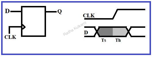
  1. Consider a D flip flop as shown in the above diagram. Here, input D is given to the flip flop, Q is the output, and clk is the clock cycle.
  2. In the waveform shown above, region one is the setup time region and region two is the hold time region.
  3. The setup time is the interval before the clock where the data must be held stable for the data to be latched correctly. Similarly, hold time is the interval after the clock where the data must be held stable.
  4. Here, the input D must remain stable and not change in the setup time before the clock occurs and it must also remain stable after the clock edge has occurred in region two i.e., during hold time.
  5. Aperture time can be defined as the total interval where input must remain stable which is setup time + hold time hence the flip flop must be stable during its aperture time.

- But why should it remain stable?

To understand this, we will consider 3 states as follow:

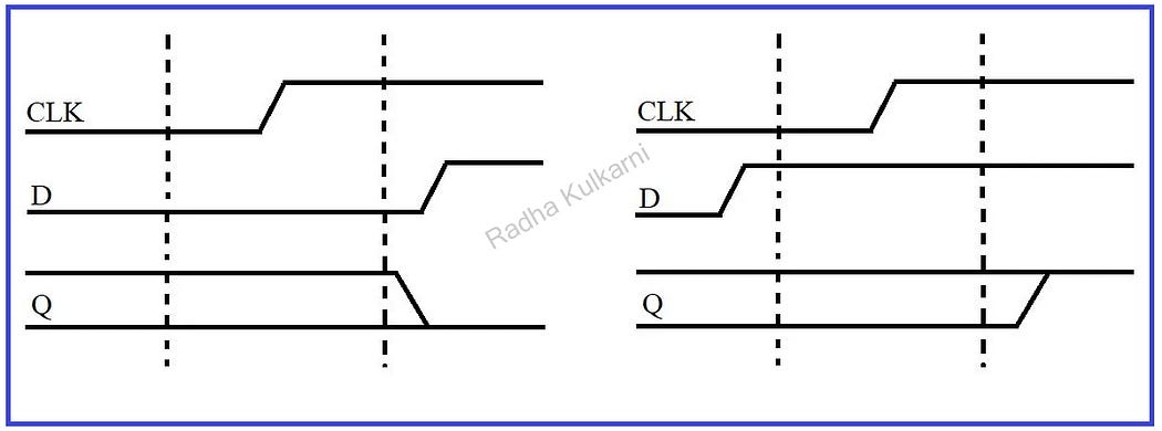
1] Consider that the input of the flip flop is stable for low value during aperture time. Then the output will take a low value.
2] Similarly, if the input of the flip flop is high in the aperture time, then the output will take a high value. This can be seen in the below diagram:

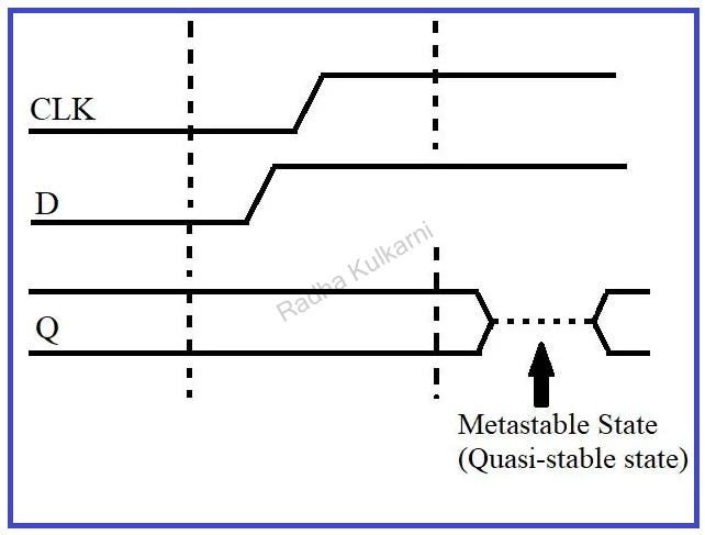
3] But if the input of the flip flop changes to a high or low value during the aperture time then the flip flop captures a value partway between low and high and this state is called the Metastable state or Quasi-stable state. This can be summarized in the below diagram.

The output will eventually take a high or a low value, but it will unlimited amount of time to settle or resolve to a good high or low value.

This process of flip-flop going into a metastable state and then getting into a high or a low state is called Metastability.

- Significance in VLSI Design:

Understanding setup time and hold time is crucial in VLSI design for several reasons:

  1. Timing Violations: Violating setup or hold time constraints can result in timing violations, leading to unreliable circuit operation and potential malfunctions.
  2. Metastability: Insufficient setup and hold times can cause metastability, where the flip-flop enters an unstable state, potentially resulting in incorrect output values.
  3. Clock Skew: Setup and hold times are affected by clock skew, which is the variation in arrival times of the clock signal at different parts of the circuit. Managing clock skew is essential to ensure proper setup and hold times are met.
  4. Performance and Reliability: Meeting setup and hold time requirements improves the overall performance and reliability of digital circuits, especially in high-speed designs.

Best Practices for Setup and Hold Time:

  1. Timing Analysis: Perform detailed timing analysis using EDA (Electronic Design Automation) tools to ensure that setup and hold time requirements are met under various operating conditions and corner cases.
  2. Clock Domain Crossing (CDC) Analysis: Pay special attention to signals crossing between different clock domains to prevent setup and hold time violations due to asynchronous interactions.
  3. Margin Consideration: Provide sufficient margin for setup and hold times to account for process variations, temperature changes, and voltage fluctuations, ensuring robust circuit operation across different conditions.

- Conclusion:

Setup time and hold time are critical concepts in VLSI design, ensuring the reliable and accurate operation of digital circuits. By understanding these timing parameters, engineers can design high-performance, robust, and error-free VLSI systems. Incorporating best practices, thorough timing analysis, and careful consideration of clock domains are key to meeting setup and hold time requirements effectively.

Like, Share and follow me if you like my content.
Thank You!

March 28, 2023

The Impact of Metastability on Digital Circuits: Flip Flops Unveiled

  • Metastability in flip-flops can be defined as the state when the output of the flip-flop oscillates between high and low values. It can be understood using setup time and hold time.
  • The concept of setup time and hold time mainly occurs while performing static timing analysis.
  • Let us consider an example of flip flop to understand setup time and hold time and why they are important in understanding metastability.
  • 1] Consider a D flip flop as shown in the above diagram. Here, input D is given to the flip flop, Q is the output, and clk is the clock cycle.
    2] In the waveform shown above, region one is the setup time region and region two is the hold time region.
    3] The setup time is the interval before the clock where the data must be held stable for the data to be latched correctly. Similarly, hold time is the interval after the clock where the data must be held stable.
    4] Here, the input D must remain stable and not change in the setup time before the clock occurs and it must also remain stable after the clock edge has occurred in region two i.e., during hold time.
    5] Aperture time can be defined as the total interval where input must remain stable which is setup time + hold time hence the flip flop must be stable during its aperture time.

    • But why should it remain stable?

    To understand this, we will consider 3 states as follow:

    1] Consider that the input of the flip flop is stable for low value during aperture time. Then the output will take a low value. Similarly, if the input of the flip flop is high in the aperture time, then the output will take a high value. This can be seen in the below diagram:

    2] But if the input of the flip flop changes to a high or low value during the aperture time then the flip flop captures a value partway between low and high and this state is called the Metastable state or Quasi-stable state. This can be summarized in the below diagram.

    The output will eventually take a high or a low value, but it will unlimited amount of time to settle or resolve to a good high or low value.

    This process of flip-flop going into a metastable state and then getting into a high or a low state is called metastability.

    • Causes:

    1] Set up time and hold time are not met for the system.
    2] If the input to flip flop is asynchronous.
    3] Input through a button or two flip flops connected together with the same frequency but in different phases.

    • Why is it important?

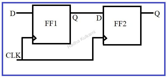
    1] Consider if two flip flops are connected one after the other as shown in the below diagram and output of 1st flip flop is given as input to the other flip flop. If the first flip-flop goes into a metastable state and cannot resolve the output to a low or high value then it will cause an error for the next flip-flop.

    • Solution:

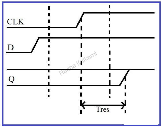
    1] Resolution Time (Tres):
    The time taken by the flip flop to resolve into a high or low state, measured from the clock edge is called as Resolution time (Tres).
    The below diagrams show the resolution time.

    The longer the resolution time greater is the chance for our system to fail.

    2] Synchronizer:
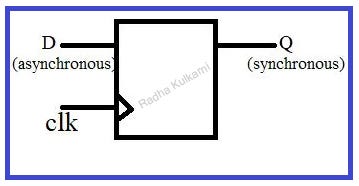
    Synchronizers use the concept of resolution time to ensure only good and stable logics goes into the system. Synchronizer uses an asynchronous input D, clock, and output Q which is synchronous with the systems clock domain.

    If the input D is stable during the aperture time, the output of synchronizer Q will be equal to D but if D is changing during aperture time Q can be either zero or one but must not be in a metastable state in this way a synchronizer works.

    Let us understand synchronizer by considering an example:

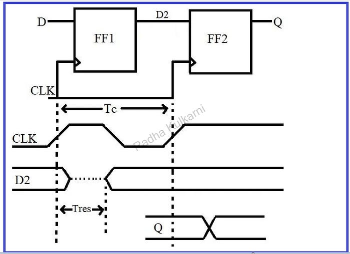
    A simple synchronizer can be made using two flip flops connecting back-to-back having the same clock as this system. If D is stable during aperture time D2 and Q will be equal to D after one clock cycle. But if input D changes during aperture time D2 will go into the metastable state if the time Tc is large enough then D2 will resolve into a stable value with high probability. The 2nd flip flop will now sample D2 which is stable so Q will be stable. Here, Tres is the resolution time.

    If D2 doesn’t resolve into any stable or valid value during time Tc it will cause Q to go into a metastable state and the synchronizer will fail.

    MTBF — mean time between failure:
    This indicates how often the given design can fail, i.e., what is the average time between two successive failures it should be as high as possible.

Like, Share and Follow me if you like my content.
Thank You.

Explore Our Topics!

Check out the extensive list of topics we discuss:  Communication Protocols: -  USB   - RS232   -  Ethernet   -  AMBA Protocol: APB, AHB and...