Showing posts with label ASIC. Show all posts

September 4, 2024

Mastering Verilog: Part 9 — Diving into Tasks and Functions

In our ongoing journey to master Verilog, we’ve explored various foundational concepts and advanced features. In this segment, we will focus on two crucial constructs in Verilog programming: Tasks and Functions. Understanding these constructs is essential for creating modular, reusable, and efficient Verilog code.

1. Introduction to Tasks and Functions

Tasks and functions in Verilog are used to encapsulate and reuse code. They help in organizing code into manageable pieces, making it more readable and maintainable. While both tasks and functions serve similar purposes, they have distinct characteristics and use cases.

Often, we encounter repetitive code segments in RTL (Register Transfer Level) that are invoked multiple times. These segments typically do not consume simulation time and often involve complex calculations with varying data values. In such instances, declaring a function to encapsulate the repetitive code can be highly beneficial. A function allows you to process inputs and return a single value, reducing the amount of RTL code you need to write. By calling the function and passing the necessary data for computation, you streamline your code and avoid redundancy.

In contrast, a task is more versatile. Tasks can handle multiple result values, returning them through output or inout arguments. They can include simulation time-consuming elements like ‘@’ or ‘posedge’. While functions do not consume simulation time and return only a single value, tasks may or may not consume simulation time and can return values via output or inout arguments.

Verilog Tasks

A task in Verilog is used to perform a sequence of statements and can include delays and timing control. Tasks are useful for operations that may require multiple statements and potentially involve waiting periods.

Syntax:

task task_name;
// Input and output declarations
input [width-1:0] input_name;
output [width-1:0] output_name;

// Task body
begin
// Task operations
end
endtask

Example:

module TaskExample;
reg [7:0] a, b;
reg [7:0] result;

// Task Definition
task add_two_numbers;
input [7:0] num1, num2;
output [7:0] sum;
begin
#5 sum = num1 + num2; // Perform addition with a delay
end
endtask

initial begin
a = 8'd10;
b = 8'd20;
add_two_numbers(a, b, result); // Call the task
$display(“The result of addition is: %d”, result);
$stop;
end
endmodule

Explanation:
Task Definition: ‘add_two_numbers’ takes two inputs (‘num1’ and ‘num2’) and provides an output (‘sum’), with a delay of 5 time units before computing the sum.
Task Call: The task is invoked in the ‘initial’ block to perform the addition.

Key Features of Tasks:
- Can contain delays and timing controls.
- Can have input, output, and inout arguments.
- Can call other tasks.
- May or may not consume simulation time, depending on their contents.

Verilog Functions

A function in Verilog is used for computing a value and returning it. Functions are typically used for simple calculations and must return a single value. They cannot contain delays or timing controls.

Syntax:

function [return_width-1:0] function_name;
input [input_width-1:0] input_name;
// Function body
begin
function_name = expression; // Compute and return value
end
endfunction

Example:

module FunctionExample;
reg [7:0] a, b;
reg [7:0] result;

// Function Definition
function [7:0] add_two_numbers;
input [7:0] num1, num2;
begin
add_two_numbers = num1 + num2; // Compute the sum
end
endfunction

initial begin
a = 8'd15;
b = 8'd25;
result = add_two_numbers(a, b); // Call the function
$display(“The result of addition is: %d”, result);
$stop;
end
endmodule

Explanation:
Function Definition: ‘add_two_numbers’ takes two inputs and returns their sum.
Function Call: The function is called in the ‘initial’ block to compute and return the result.

Key Features of Functions:
- Cannot contain delays or timing controls.
- Must return a single value.
- Cannot call tasks.
- Can be used within expressions.

Differences Between Tasks and Functions
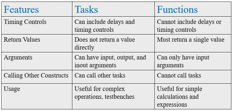
Practical Examples

  1. Task Example
    Suppose you are designing a complex digital system where you need to perform a sequence of operations with delays. A task can be used to encapsulate this logic and improve code readability.
  2. Function Example
    For simple calculations such as computing a checksum or performing bitwise operations, functions can be used within expressions to streamline your code.

Conclusion

Tasks and functions are powerful constructs in Verilog that enable modular, reusable, and efficient coding practices. Tasks are suited for complex operations with timing controls, while functions are ideal for simple computations. By encapsulating repetitive code segments in functions and leveraging tasks for more complex operations, you can enhance code maintainability and efficiency. Mastering these constructs will elevate your ability to design and verify digital systems effectively.

Stay tuned for more insights and advanced topics in our mastering Verilog series!

July 28, 2024

VLSI Insights: Frequently Asked Questions Uncovered

In this blog post, we delve into the most frequently asked questions about VLSI (Very Large Scale Integration). Whether you’re a beginner exploring the world of semiconductor design or an experienced engineer looking for insights, these FAQs cover key aspects of VLSI that are crucial to understand.

  1. What are the key differences between ASIC and FPGA?
  2. What are Flip-Flops and how do they differ from Latches?
  3. Explain the concept of clock skew and how it affects digital circuits.
  4. What are the different types of memories used in VLSI systems?
  5. What is metastability in digital circuits, and how is it handled?
  6. Explain the concept of Moore’s Law and its impact on VLSI technology.
  7. How does USB data transfer work, including the host-slave architecture, addressing and data signals?
  8. What is Twin Tub CMOS technology and how does it work?
  9. How many transistors do a Static RAM ?
  10. Discuss the role of EDA (Electronic Design Automation) tools in VLSI design.
  11. What is Verilog? How is it different from normal programming languages?
  12. How can we use BJT as a switch?
  13. What are the basic logic gates and their functions?
  14. How does Boolean algebra apply to logic circuit design?
  15. Explain the working principle of DRAM and SRAM.
  16. What are registers and their role in digital circuits.
  17. Can you explain the AMBA protocol: APB, AHB and ASB?
  18. What are the 12 important concepts you need to know when designing a chip?
  19. What are Signal Integrity and Crosstalk Effect in VLSI circuits?
  20. What is the antenna effect in VLSI, and how can it be mitigated? 
  21. What are the differences between UART, I2C, and SPI communication protocols?
  22. How does the RS232 protocol differ from other serial communication protocols?
  23. What is the Ethernet communication protocol and how does it function?
  24. How do counters work in sequential circuits?
  25. What are the different types of transistors used in VLSI?
  26. What are the key components of an FPGA's architecture?
  27. What are the two primary VLSI design methodologies?
  28. Describe the basic rules for designing logic circuits in CMOS technology.
  29. Explain the design flow in VLSI.
  30. What are the two operating modes of dynamic CMOS, and how do they function?
  31. Why mux is called universal logic selector?
  32. Why mux is called data selector?
  33. What are differences between Multiplexer(MUX) and Demultiplexer(DEMUX)?
  34. What is the difference between synchronous and asynchronous circuits?
  35. How do setup and hold times affect circuit design?
  36. What is the difference between static and dynamic power consumption in VLSI?
  37. What is the role of parasitic capacitance in VLSI circuits?
  38. What is the importance of Design for Testability (DFT) in VLSI?
  39. Explain the concept of pipelining in digital circuits.
  40. What is the difference between CMOS and BiCMOS technologies?
  41. Explain the differece between behavioral and structural modeling in HDL.
  42. What is the difference between RTL (Register Transfer Level) and gate-level design?
  43. What is the role of floorplanning in VLSI design?
  44. What is the difference between Analog and Digital VLSI design?
  45. Explain the concept of Latch-up in CMOS circuits and how it can be prevented.
  46. What is the difference between microprocessor ad microcontroller in VLSI?
  47. What is the purpose of decoupling capacitor in a digital circuit?
  48. What is a System-On-Chip?
  49. What is the difference between Hard IP and Soft IP in VLSI?
  50. What do you understand by DCMs? Why are they used?
  51. What is timing closure in VLSI design, and why is it important?

Have more questions about VLSI? Drop them in the comments, and we’ll do our best to provide answers.

March 1, 2024

ASIC vs FPGA: Unveiling the Key Differences and Applications


  • In the realm of digital circuit design, two prominent technologies stand out: Application-Specific Integrated Circuits (ASICs) and Field-Programmable Gate Arrays (FPGAs). Each offers unique capabilities and is suited to different applications. This blog post delves into the comparative analysis of ASICs and FPGAs, shedding light on their advantages, disadvantages, and typical use cases.
  • The origins of ASICs and FPGAs trace back to distinct trajectories in the evolution of semiconductor technology. ASICs emerged as highly specialized integrated circuits tailored to specific applications, with their roots dating back to the early days of custom chip design.
  • Conversely, FPGAs arose as programmable logic devices, offering flexibility and reconfigurability to designers. Over time, both technologies have undergone significant advancements, catering to a broad spectrum of applications across industries.
  • Let’s break down the key differences between ASICs and FPGAs across various dimensions:

1] ASIC:

  • ASIC stands for Application-Specific Integrated Circuit. An ASIC is a type of integrated circuit (IC) customized for a specific application or use case. ASICs are created by designing and fabricating a semiconductor chip that integrates various electronic components and functionalities required for a specific application onto a single silicon die.
  • Unlike FPGAs, which are reconfigurable, ASICs are fabricated for a singular purpose, offering unparalleled performance and power efficiency. ASICs undergo a rigorous design process, including layout, fabrication, and testing, resulting in optimized solutions tailored to precise requirements.
  • ASICs can be further classified into two main categories:
  1. Full-Custom ASICs: In full-custom ASICs, every aspect of the design, including the layout of transistors and interconnects, is customized to meet the specific requirements of the application. Full-custom designs offer the highest level of performance and power efficiency but require significant time, expertise, and resources to develop.
  2. Semi-Custom ASICs: Semi-custom ASICs, also known as application-specific standard products (ASSPs), utilize pre-designed and pre-verified intellectual property (IP) blocks or modules, which are combined and configured to meet the application’s requirements. Semi-custom ASICs strike a balance between customization and time-to-market, offering faster development cycles and lower upfront costs compared to full-custom designs.
  1. Performance: ASICs excel in performance-critical applications, offering high-speed operation and low latency.
  2. Power Efficiency: With optimized designs and tailored architectures, ASICs minimize power consumption, making them ideal for battery-operated devices.
  3. Cost Efficiency: Despite higher initial development costs, ASICs can be more cost-effective in mass production scenarios due to lower per-unit costs.
  4. Security: ASICs provide enhanced security as their fixed designs make reverse engineering and tampering challenging.
  • Disadvantages of ASICs:
  1. NRE Costs: Non-Recurring Engineering (NRE) costs associated with ASIC development, including design, fabrication, and testing, can be substantial.
  2. Time to Market: ASIC development cycles are typically longer than FPGAs, resulting in extended time to market.
  3. Lack of Flexibility: Once fabricated, ASIC designs cannot be modified, limiting adaptability to changing requirements.
  4. Prototyping Challenges: Prototyping ASIC designs can be expensive and time-consuming, often requiring emulation or FPGA-based prototypes.
  • Typical Applications of ASICs:

ASICs are commonly used in a variety of industries, including telecommunications, automotive, aerospace, consumer electronics, and healthcare. They are deployed in diverse applications such as signal processing, data encryption, sensor interfaces, motor control, and networking equipment.

2] FPGA:

  • FPGA, which stands for Field Programmable Gate Array, represents a programmable logic device allowing users to program or reprogram it post-manufacturing to meet specific requirements. Comprising a set of programmable logic blocks and interconnects, an FPGA can be tailored to execute a diverse range of digital operations.
  • FPGAs are commonly programmed through Hardware Description Languages (HDLs) like VHDL (VHSIC Hardware Description Language) or Verilog, empowering designers to articulate the intended behavior of the digital circuits they aim to realize.
  • Click the link below for a comprehensive understanding of FPGAs:
    FPGA Insights: From Concept to Configuration
  • Advantages of FPGAs:
  1. Flexibility: FPGAs offer reconfigurability, allowing designers to implement and iterate designs quickly without the need for mask changes.
  2. Rapid Prototyping: FPGAs facilitate rapid prototyping, enabling designers to test and validate designs before committing to ASIC fabrication.
  3. Time to Market: FPGAs reduce time to market by enabling fast design iterations and prototyping, especially in dynamic market environments.
  4. Low NRE Costs: FPGAs eliminate the high upfront NRE costs associated with ASIC development, making them suitable for low-volume production and niche markets.
  • Disadvantages of FPGAs:
  1. Performance Limitations: FPGAs typically offer lower performance and higher power consumption compared to ASICs for equivalent tasks.
  2. Resource Constraints: FPGAs have finite resources (logic cells, memory, DSP blocks), which may limit the complexity and scale of designs.
  3. Cost per Unit: FPGAs can be more expensive per unit compared to ASICs for high-volume production runs.
  4. Security Concerns: FPGAs may be susceptible to security vulnerabilities such as bitstream manipulation and side-channel attacks.
  • Typical Applications of FPGAs:
  1. Prototyping and validation of ASIC designs in the early stages of development.
  2. Digital signal processing (DSP) applications including audio/video processing, communication systems, and image processing.
  3. Reconfigurable computing platforms for research, education, and experimentation.

In summary, both ASICs and FPGAs have their own strengths and are used for different jobs in digital circuit design. ASICs are like specialized experts — they’re really good at specific tasks, are energy efficient, and are hard to tamper with. On the other hand, FPGAs are more like versatile tools — they’re flexible, great for trying out new ideas quickly, and can be cheaper for smaller projects.

Deciding between ASICs and FPGAs depends on what you need for your project — like how fast it needs to be, how much money you have, and how quickly you need to finish. By understanding what each one is good at, engineers can choose the right tool for the job. Whether it’s making cars safer or building better computers, both ASICs and FPGAs help us create new and amazing things, shaping the future of technology.

Like, Share and Follow me if you like my content.
Thank You.

Explore Our Topics!

Check out the extensive list of topics we discuss:  Communication Protocols: -  USB   - RS232   -  Ethernet   -  AMBA Protocol: APB, AHB and...