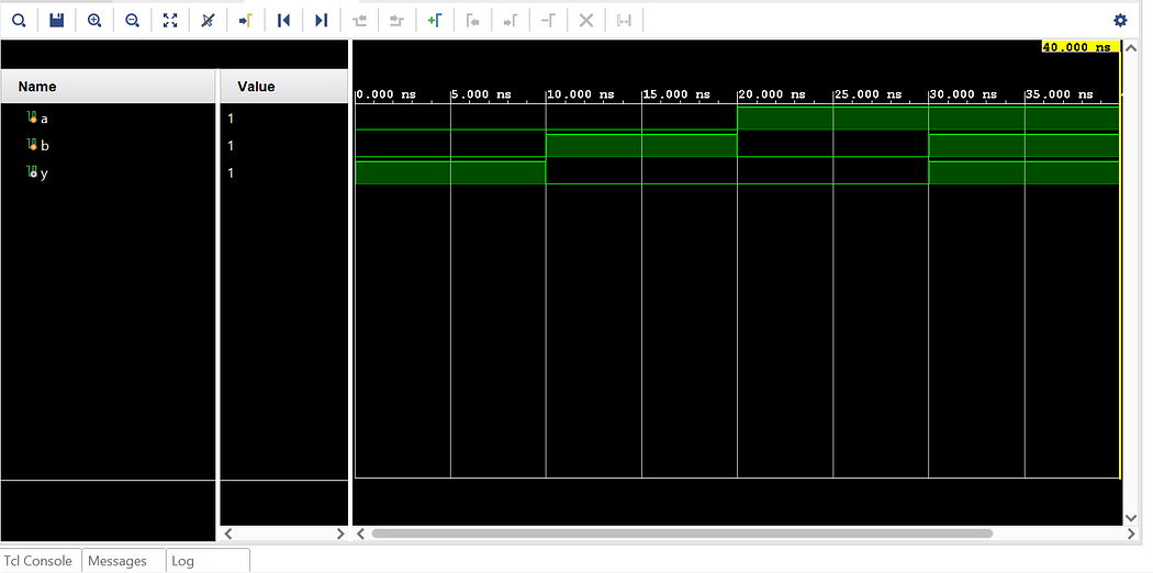
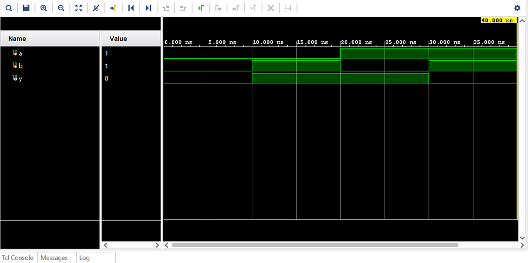
Showing posts with label testbench. Show all posts

September 4, 2024

Mastering Verilog: Part 9 — Diving into Tasks and Functions

In our ongoing journey to master Verilog, we’ve explored various foundational concepts and advanced features. In this segment, we will focus on two crucial constructs in Verilog programming: Tasks and Functions. Understanding these constructs is essential for creating modular, reusable, and efficient Verilog code.

1. Introduction to Tasks and Functions

Tasks and functions in Verilog are used to encapsulate and reuse code. They help in organizing code into manageable pieces, making it more readable and maintainable. While both tasks and functions serve similar purposes, they have distinct characteristics and use cases.

Often, we encounter repetitive code segments in RTL (Register Transfer Level) that are invoked multiple times. These segments typically do not consume simulation time and often involve complex calculations with varying data values. In such instances, declaring a function to encapsulate the repetitive code can be highly beneficial. A function allows you to process inputs and return a single value, reducing the amount of RTL code you need to write. By calling the function and passing the necessary data for computation, you streamline your code and avoid redundancy.

In contrast, a task is more versatile. Tasks can handle multiple result values, returning them through output or inout arguments. They can include simulation time-consuming elements like ‘@’ or ‘posedge’. While functions do not consume simulation time and return only a single value, tasks may or may not consume simulation time and can return values via output or inout arguments.

Verilog Tasks

A task in Verilog is used to perform a sequence of statements and can include delays and timing control. Tasks are useful for operations that may require multiple statements and potentially involve waiting periods.

Syntax:

task task_name;
// Input and output declarations
input [width-1:0] input_name;
output [width-1:0] output_name;

// Task body
begin
// Task operations
end
endtask

Example:

module TaskExample;
reg [7:0] a, b;
reg [7:0] result;

// Task Definition
task add_two_numbers;
input [7:0] num1, num2;
output [7:0] sum;
begin
#5 sum = num1 + num2; // Perform addition with a delay
end
endtask

initial begin
a = 8'd10;
b = 8'd20;
add_two_numbers(a, b, result); // Call the task
$display(“The result of addition is: %d”, result);
$stop;
end
endmodule

Explanation:
Task Definition: ‘add_two_numbers’ takes two inputs (‘num1’ and ‘num2’) and provides an output (‘sum’), with a delay of 5 time units before computing the sum.
Task Call: The task is invoked in the ‘initial’ block to perform the addition.

Key Features of Tasks:
- Can contain delays and timing controls.
- Can have input, output, and inout arguments.
- Can call other tasks.
- May or may not consume simulation time, depending on their contents.

Verilog Functions

A function in Verilog is used for computing a value and returning it. Functions are typically used for simple calculations and must return a single value. They cannot contain delays or timing controls.

Syntax:

function [return_width-1:0] function_name;
input [input_width-1:0] input_name;
// Function body
begin
function_name = expression; // Compute and return value
end
endfunction

Example:

module FunctionExample;
reg [7:0] a, b;
reg [7:0] result;

// Function Definition
function [7:0] add_two_numbers;
input [7:0] num1, num2;
begin
add_two_numbers = num1 + num2; // Compute the sum
end
endfunction

initial begin
a = 8'd15;
b = 8'd25;
result = add_two_numbers(a, b); // Call the function
$display(“The result of addition is: %d”, result);
$stop;
end
endmodule

Explanation:
Function Definition: ‘add_two_numbers’ takes two inputs and returns their sum.
Function Call: The function is called in the ‘initial’ block to compute and return the result.

Key Features of Functions:
- Cannot contain delays or timing controls.
- Must return a single value.
- Cannot call tasks.
- Can be used within expressions.

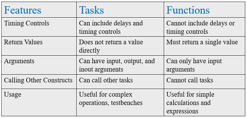
Differences Between Tasks and Functions
Practical Examples

  1. Task Example
    Suppose you are designing a complex digital system where you need to perform a sequence of operations with delays. A task can be used to encapsulate this logic and improve code readability.
  2. Function Example
    For simple calculations such as computing a checksum or performing bitwise operations, functions can be used within expressions to streamline your code.

Conclusion

Tasks and functions are powerful constructs in Verilog that enable modular, reusable, and efficient coding practices. Tasks are suited for complex operations with timing controls, while functions are ideal for simple computations. By encapsulating repetitive code segments in functions and leveraging tasks for more complex operations, you can enhance code maintainability and efficiency. Mastering these constructs will elevate your ability to design and verify digital systems effectively.

Stay tuned for more insights and advanced topics in our mastering Verilog series!
November 2, 2023

Verilog - NOT Gate

 not_gate.v

module and_gate(a,y);
input a;
output y;

not(y,a);
endmodule

tb_not_gate.v

module tb_not_gate;
reg a;
wire y;

not_gate UUT (.a(a), .y(y));

initial begin
$display(“Testing NOT gate”);

a = 0;
#10;
$display(“Input_A = %b, Output = %b”, a,y);

a = 1;
#10;
$display(“Input_A = %b, Output = %b”, a,y);

$finish;
end
endmodule

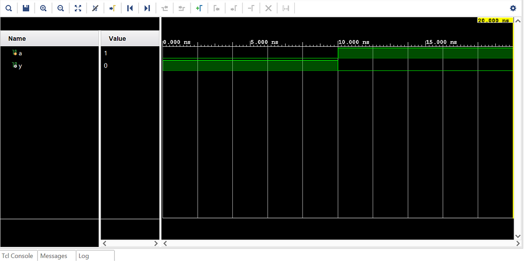
The output waveform for not gate will be as follows:


Verilog - XNOR Gate

 xnor_gate.v

module xnor_gate(a,b,y);
input a;
input b;
output y;

xnor(y,a,b);
endmodule

tb_xnor_gate.v

module tb_xnor_gate;
reg a;
reg b;
wire y;

xnor_gate UUT (.a(a), .b(b), .y(y));

initial begin
$display(“Testing XNOR gate”);

a = 0; b=0;
#10;
$display(“Input_A = %b, Input_B = %b, Output = %b”, a,b,y);

a = 0; b=1;
#10;
$display(“Input_A = %b, Input_B = %b, Output = %b”, a,b,y);

a = 1; b=0;
#10;
$display(“Input_A = %b, Input_B = %b, Output = %b”, a,b,y);

a = 1; b=1;
#10;
$display(“Input_A = %b, Input_B = %b, Output = %b”, a,b,y);

$finish;
end
endmodule

The output waveform for xnor gate will be as follows:


Verilog - XOR Gate

 xor_gate.v

module xor_gate(a,b,y);
input a;
input b;
output y;

xor(y,a,b);
endmodule

tb_xor_gate.v

module tb_xor_gate;
reg a;
reg b;
wire y;

xor_gate UUT (.a(a), .b(b), .y(y));

initial begin
$display(“Testing XOR gate”);

a = 0; b=0;
#10;
$display(“Input_A = %b, Input_B = %b, Output = %b”, a,b,y);

a = 0; b=1;
#10;
$display(“Input_A = %b, Input_B = %b, Output = %b”, a,b,y);

a = 1; b=0;
#10;
$display(“Input_A = %b, Input_B = %b, Output = %b”, a,b,y);

a = 1; b=1;
#10;
$display(“Input_A = %b, Input_B = %b, Output = %b”, a,b,y);

$finish;
end
endmodule

The output waveform for xor gate will be as follows:


Verilog - NOR Gate

 nor_gate.v

module nor_gate(a,b,y);
input a;
input b;
output y;

nor(y,a,b);
endmodule

tb_nor_gate.v

module tb_nor_gate;
reg a;
reg b;
wire y;

nor_gate UUT (.a(a), .b(b), .y(y));

initial begin
$display(“Testing NOR gate”);

a = 0; b=0;
#10;
$display(“Input_A = %b, Input_B = %b, Output = %b”, a,b,y);

a = 0; b=1;
#10;
$display(“Input_A = %b, Input_B = %b, Output = %b”, a,b,y);

a = 1; b=0;
#10;
$display(“Input_A = %b, Input_B = %b, Output = %b”, a,b,y);

a = 1; b=1;
#10;
$display(“Input_A = %b, Input_B = %b, Output = %b”, a,b,y);

$finish;
end
endmodule

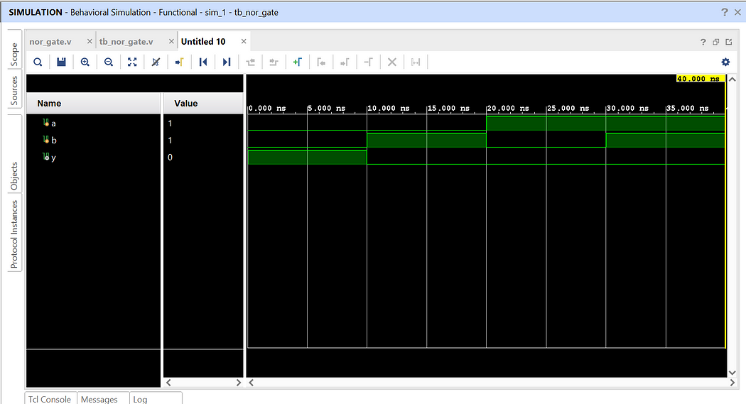
The output waveform for nor gate will be as follows:


Verilog - NAND Gate

 nand_gate.v

module nand_gate(a,b,y);
input a;
input b;
output y;

nand(y,a,b);
endmodule

tb_nand_gate.v

module tb_nand_gate;
reg a;
reg b;
wire y;

nand_gate UUT (.a(a), .b(b), .y(y));

initial begin
$display("Testing NAND gate");

a = 0; b=0;
#10;
$display("Input_A = %b, Input_B = %b, Output = %b", a,b,y);

a = 0; b=1;
#10;
$display("Input_A = %b, Input_B = %b, Output = %b", a,b,y);

a = 1; b=0;
#10;
$display("Input_A = %b, Input_B = %b, Output = %b", a,b,y);

a = 1; b=1;
#10;
$display("Input_A = %b, Input_B = %b, Output = %b", a,b,y);

$finish;
end
endmodule

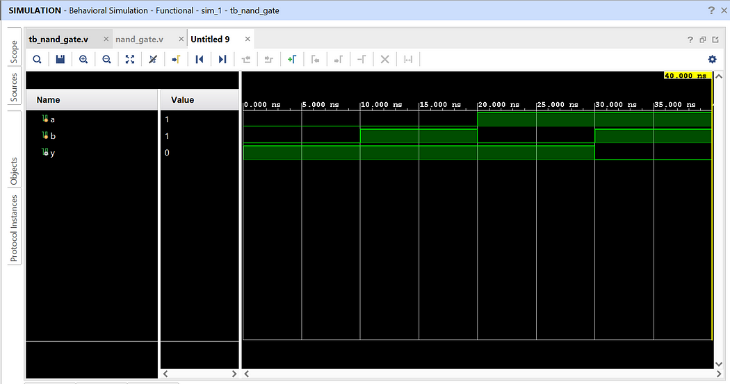
The output waveform for nand gate will be as follows:


Verilog - Or Gate

 or_gate.v

module or_gate(a,b,y);
input a;
input b;
output y;

or(y,a,b);
endmodule

tb_or_gate.v

module tb_or_gate;
reg a;
reg b;
wire y;

or_gate UUT (.a(a), .b(b), .y(y));

initial begin
$display(“Testing OR gate”);

a = 0; b=0;
#10;
$display(“Input_A = %b, Input_B = %b, Output = %b”, a,b,y);

a = 0; b=1;
#10;
$display(“Input_A = %b, Input_B = %b, Output = %b”, a,b,y);

a = 1; b=0;
#10;
$display(“Input_A = %b, Input_B = %b, Output = %b”, a,b,y);

a = 1; b=1;
#10;
$display(“Input_A = %b, Input_B = %b, Output = %b”, a,b,y);

$finish;
end
endmodule

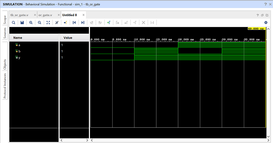
The output waveform for or gate will be as follows:


Step-by-step guide on how to design and implement Logic Gates with testbench code on Xilinx Vivado design tool using Verilog HDL.

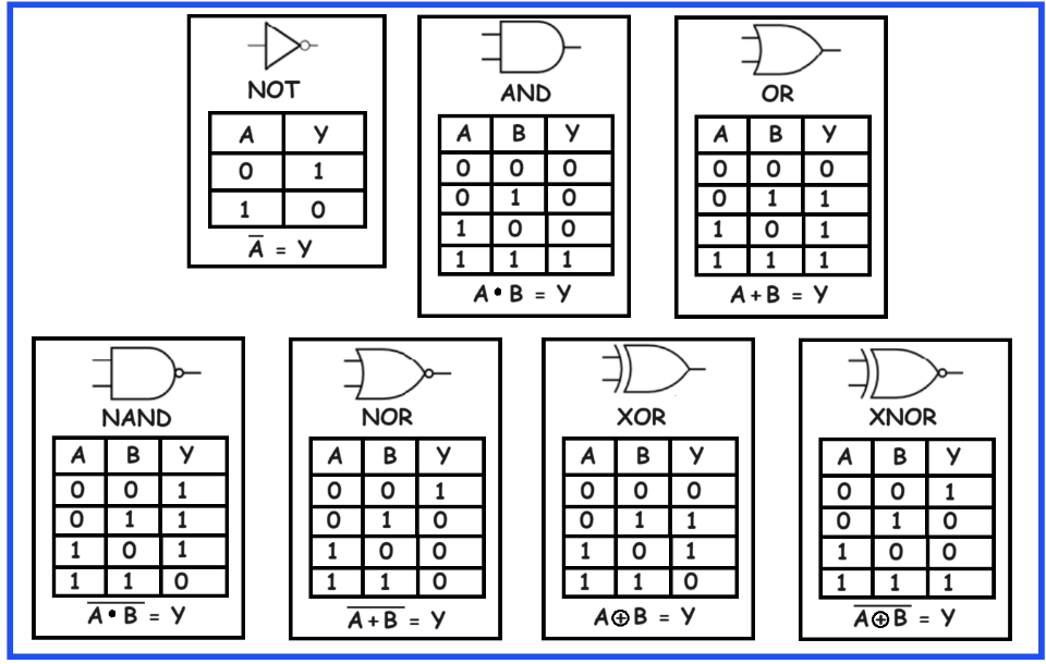
 In this project, we will see how to implement all logic gates with verilog testbench code on Xilinx Vivado design tool. Below diagram shows all logic gates along with there truth tables, symbol and Boolean equation.

Now let us see how we will implement these gates using Xilinx Vivado design tool.

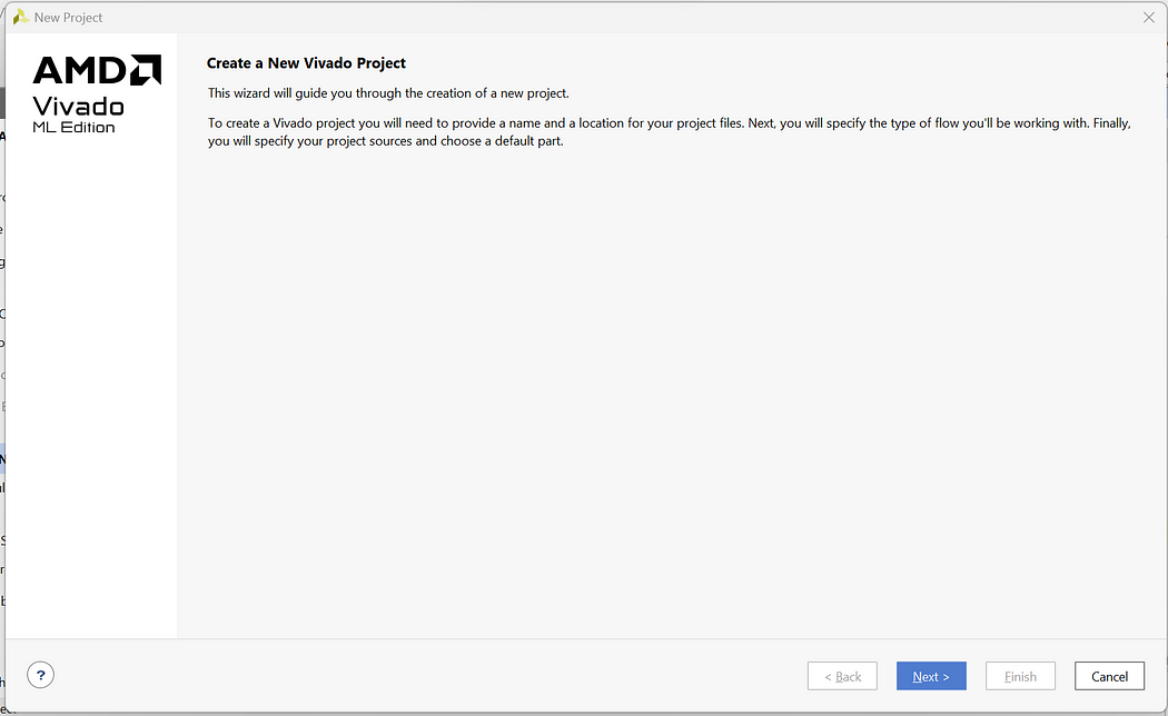
Step 1: Click on New Project -> Next

Step 2: Enter Project Name and Select appropriate Project Location -> Next

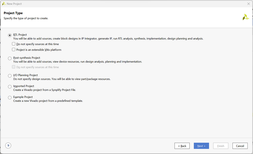
Step 3: Select RTL Project -> Next

Step 4: Click on Create File and create file with file name and_gate -> Next

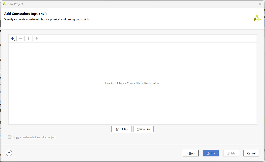
Step 5: We will not add the Constraint file So click on Next

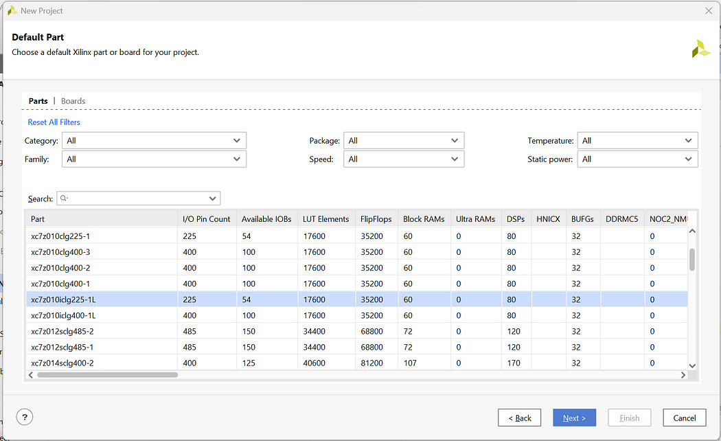
Step 6: For Default Part click on Next as we are not using any development Board

Step 7: Check the New Project Summary and click on Finish.

Step 8: Now you will be prompted with the Define module page but we will create the complete code from scratch so click on cancel and Yes

Step 9: Now on the Home Page click on Sources -> Design Sources -> Non-module Files

Step 10: Enter the below codes in the “and_gate.v” files.

and_gate.v

module and_gate(a,b,y);
input a;
input b;
output y;

and(y,a,b);
endmodule

Step 11: Now to write the testbench code for and gate right click on Design Sources -> Add Sources -> Add or create design sources -> Create File -> Add File name as tb_and_gate -> Finish -> Ok -> Yes

Step 12: Now open the testbench file and enter the below testbench code

module tb_and_gate;
reg a;
reg b;
wire y;

and_gate UUT (.a(a), .b(b), .y(y));

initial begin
$display(“Testing AND gate”);

a = 0; b=0;
#10;
$display(“Input_A = %b, Input_B = %b, Output = %b”, a,b,y);

a = 0; b=1;
#10;
$display(“Input_A = %b, Input_B = %b, Output = %b”, a,b,y);

a = 1; b=0;
#10;
$display(“Input_A = %b, Input_B = %b, Output = %b”, a,b,y);

a = 1; b=1;
#10;
$display(“Input_A = %b, Input_B = %b, Output = %b”, a,b,y);

$finish;
end
endmodule

Here, in testbench code we do not define values in entity hence we have kept it empty. Then in architecture we have copied the components of and_gate and defined signals for connecting the ports of and gate. Inside the process statement we write all 4 test cases from truth table and define the delay as 100ns.

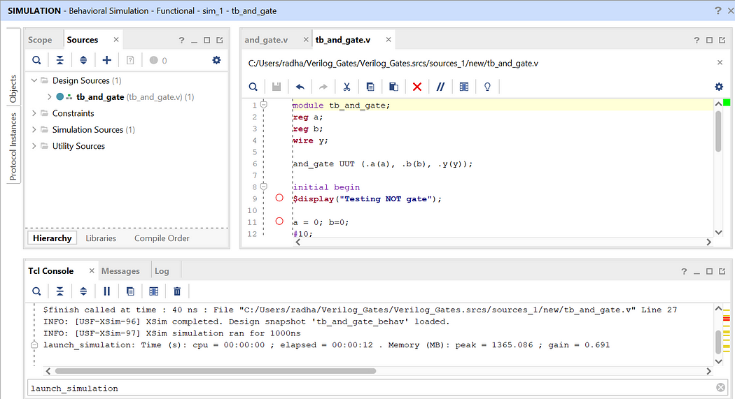
Step 13: Now as we have written all the codes let’s launch the simulation. Enter launch_simulation in the Tcl Console and press Enter.

We have successfully implemented and gate with testbench code. Click on Zoom Fit to see the output waveform more clearly and verify the outputs.

If we want to implement other gates the process will be same except the Verilog codes. Visit below links to see how to implement other gates:


In this way, we can implement all logic gates using testbench codes.

Like, Share, and Follow me if you like my content.
Thank You


Explore Our Topics!

Check out the extensive list of topics we discuss:  Communication Protocols: -  USB   - RS232   -  Ethernet   -  AMBA Protocol: APB, AHB and...