In digital electronics, subtraction is as essential as addition, particularly when dealing with multi-bit numbers. While the Half Subtractor covers basic single-bit subtraction, it falls short when borrow operations come into play. The Full Subtractor is designed to handle these situations, making it a crucial element in advanced digital systems. This blog post will explore the Full Subtractor, its components, operation, and significance.
What is a Full Subtractor?
A Full Subtractor is a combinational circuit that performs the subtraction of two binary bits while accounting for a borrow from a previous stage. Unlike the Half Subtractor, which handles subtraction without borrow consideration, the Full Subtractor manages both the difference and borrow efficiently in multi-bit binary subtraction. It produces two outputs:
- Difference (D)
- Borrow (B_out)
Theoretical Background
Let’s revisit the rules of binary subtraction, adding the case where we borrow from a previous operation:
- 0–0 = 0
- 1–0 = 1
- 1–1 = 0
- 0–1 = 1 (with a borrow of 1)
When performing multi-bit subtraction, the Full Subtractor must also consider an input borrow (B_in) from the previous less significant bit, leading to more complex calculations.
Components of a Full Subtractor
A Full Subtractor involves three binary inputs:
- A: The minuend (the number being subtracted from)
- B: The subtrahend (the number being subtracted)
- B_in: The borrow input from the previous stage
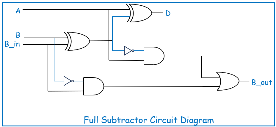
The Full Subtractor employs the following logic gates:
- XOR Gates: To compute the difference
- AND and OR Gates: To compute the borrow output
The logic expressions for the outputs are:
- Difference (D) = A ⊕ B ⊕ B_in
- Borrow out (B_out) = (A’ ANDB) OR ((A ⊕ B)’ AND B_in)
Circuit Diagram
The Full Subtractor circuit is built using the above components, showing how the XOR gates compute the difference and how the AND/OR gates handle the borrow. Here’s a simplified diagram for better understanding:

Truth Table
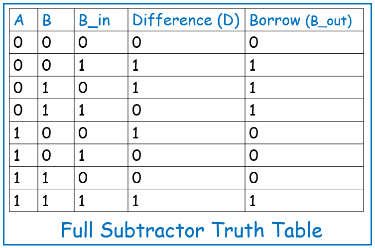
The Full Subtractor truth table details the results of all possible combinations of the three inputs (A, B, and B_in):

Applications of Full Subtractor
The Full Subtractor is vital in systems requiring multi-bit subtraction, including:
- Arithmetic Logic Units (ALUs): A core component in CPUs for handling multi-bit arithmetic operations.
- Digital Counters: Used in applications that require down-counting, where the Full Subtractor helps manage borrow operations.
- Binary Calculators: Necessary for performing precise binary arithmetic.
- Data Processing Systems: In systems requiring complex binary operations, the Full Subtractor plays a key role in ensuring accurate computations.
Conclusion
The Full Subtractor extends the functionality of the Half Subtractor by accounting for borrow operations, making it indispensable in multi-bit subtraction scenarios. Understanding the Full Subtractor’s logic and applications is essential for advancing in digital circuit design and gaining a deeper insight into how subtraction is handled in various digital systems. As you move toward more complex circuits, mastering the Full Subtractor will provide a strong foundation for future exploration in digital electronics.