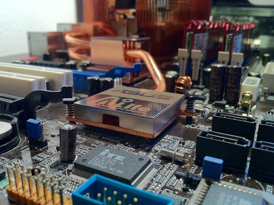
Electronics, as a field, is rich and vast, encompassing numerous sub-disciplines that serve different applications. Two of the most significant branches are Analog Electronics and Digital Electronics. These two domains form the foundation for virtually all electronic devices and systems in use today, from radios to computers, and from smartphones to complex industrial control systems.
In this blog, we will dive deep into the technical aspects of both analog and digital electronics, their components, and how they differ. By the end, you’ll have a clearer understanding of why these two areas are critical to modern technology and how they contribute to the development of advanced devices.

What is Analog Electronics?
Analog electronics deals with circuits and devices that work with continuous signals. In these systems, the signals can take on any value within a given range, making them ideal for applications that require smooth, real-time responses. Analog systems are often used in situations where physical phenomena like sound, light, or temperature need to be monitored or processed.
Key Components of Analog Electronics:
1.Resistors:
- Control the flow of current in a circuit and determine the voltage drop across components.
- Used in a variety of applications, from simple current limiting to complex filter designs.
2.Capacitors:
- Store and release electrical energy, and help smooth out voltage fluctuations.
- Commonly used in filtering applications, coupling signals, and timing circuits.
3.Inductors:
- Store energy in a magnetic field and resist changes in current.
- Frequently used in power supply filters and radio-frequency circuits.
4.Transistors:
- Act as switches or amplifiers in analog circuits.
- Bipolar Junction Transistors (BJTs) and Field-Effect Transistors (FETs) are commonly used for amplifying signals and controlling current flow.
5.Operational Amplifiers (OPAMPs):
- Versatile components used for amplifying, filtering, and processing analog signals.
- OPAMPs are the building blocks for many analog circuits, including filters, oscillators, and feedback systems.
6.Diodes:
- Control the direction of current flow, allowing current to pass in one direction only.
- Used in rectifiers, signal demodulation, and protection circuits.
Common Analog Circuit Types:
- Amplifiers: Used to boost the strength of weak signals, such as audio or radio signals.
- Oscillators: Generate periodic waveforms (e.g., sine waves, square waves) used in signal generation and clock circuits.
- Filters: Modify the frequency content of signals, removing unwanted noise or allowing certain frequencies to pass through.
What is Digital Electronics?
Digital electronics, on the other hand, deals with circuits that process binary signals — 0s and 1s. These signals are discrete, meaning they only have two possible states (high or low, true or false, 1 or 0). Digital systems are used in computing, communication, and control systems due to their precision, reliability, and ability to handle complex data processing tasks.
Key Components of Digital Electronics:
1.Logic Gates:
- The fundamental building blocks of digital circuits. Logic gates perform basic logical operations on one or more binary inputs to produce a single output.
- Common logic gates include AND, OR, NOT, NAND, NOR, XOR, and XNOR gates.
2.Flip-Flops:
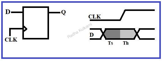
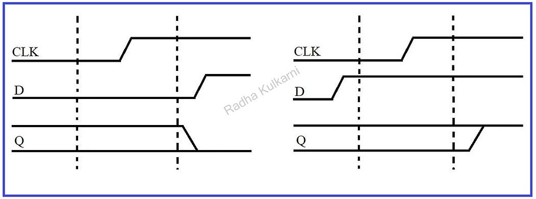
- Used for storing binary data. These circuits can store a single bit of information, making them essential for memory storage and data processing in digital systems.
- Types of flip-flops include SR flip-flop, JK flip-flop, D flip-flop, and T flip-flop.
3.Microcontrollers:
- Small computers on a chip, designed to perform specific tasks based on programmed instructions.
- Microcontrollers are central to embedded systems and control applications in appliances, robotics, automotive systems, and much more.
4.Registers:
- Small, fast storage locations in digital circuits used to hold data temporarily during processing.
- Used in processors, microcontrollers, and memory systems.
5.Counters:
- Used to count pulses or events. A counter in digital circuits can increment or decrement its value, and it is commonly used in timekeeping, frequency division, and sequence control.
6.Analog-to-Digital Converter (ADC):
- Converts continuous analog signals into discrete digital values, allowing digital systems to process real-world signals.
- Essential in applications like digital audio, sensors, and communication systems.
7.Digital-to-Analog Converter (DAC):
- Converts discrete digital values back into continuous analog signals.
- Used in audio systems, video systems, and telecommunications.
Common Digital Circuit Types:
- Combinational Circuits: These circuits perform logical operations on inputs to produce outputs without memory (e.g., adders, multiplexers).
- Sequential Circuits: These circuits rely on previous inputs and outputs to determine the next state, which makes them essential for tasks like counting and timing.
- Memory Circuits: Digital systems rely on memory elements like registers, RAM, and ROM to store and retrieve data efficiently.
Analog vs. Digital: The Key Differences
- Signal Type: Analog deals with continuous signals, whereas Digital works with discrete binary signals.
- Precision: Analog systems are subject to noise and distortion, making them less precise. Digital systems offer higher accuracy, as data is processed in binary format, reducing errors due to interference.
- Complexity: Analog systems are often simpler in terms of components, but digital systems are more scalable, powerful, and capable of handling more complex tasks due to the ability to process large amounts of data efficiently.
- Noise Resistance: Analog systems are more prone to noise and interference. Digital systems, however, are more resistant to noise, as small variations in the signal won’t affect the overall outcome.
- Applications: Analog is widely used in signal amplification, audio processing, radios, and temperature sensors. Digital electronics dominates in computing, data storage, communication systems, and signal processing.
Bridging the Gap: Analog and Digital Integration
In modern electronics, analog and digital systems often work together. For example, in a smartphone, analog components such as the microphone convert sound (an analog signal) into digital signals, which are then processed by digital circuits. The final result is transmitted as a digital signal to the speaker, where it is converted back into an analog signal. These hybrid systems make use of both Analog-to-Digital Converters (ADCs) and Digital-to-Analog Converters (DACs).
Conclusion
In conclusion, both analog and digital electronics are indispensable in today’s world of technology. Analog circuits are essential for processing real-world signals smoothly and in real-time, while digital circuits bring precision, power, and the ability to handle complex data manipulation and processing. Together, they form the backbone of everything from smartphones and computers to industrial automation systems.
If you’re an aspiring engineer or a tech enthusiast, understanding the technicalities of both branches will give you a significant advantage in comprehending the underlying principles of modern electronic systems. Whether you’re designing a simple amplifier or working on an advanced microprocessor, the integration of analog and digital systems will be crucial to your success.
Stay tuned for more deep dives into specific analog and digital components, and explore how these two branches of electronics are transforming the world around us!


