Showing posts with label flip flop. Show all posts

November 6, 2024

Explore Our Topics!

Check out the extensive list of topics we discuss: 

  1. Communication Protocols:
    USB 
    - RS232 
    Ethernet 
    AMBA Protocol: APB, AHB and ASB 
    UART, I2C AND SPI
  2. Important concepts in VLSI:
    Designing a Chip? Here Are the 12 Important Concepts You Need to Know
    Metastability 
    - Setup time and Hold time
    Signal Integrity and Crosstalk effect
    Skews and Slack 
    Antenna Effect
  3. Semiconductor Memories
  4. Most Frequently Asked Questions in VLSI
  5. Transistors:
    BJT
    JFET
    MOSFET
    CMOS
    Transmission Gate CMOS
    Dynamic CMOS
  6. Sequential Circuits:
    Registers
    Counters
    Latches
    Flip Flops
  7. FPGA:
    ASIC vs FPGA
    FPGA Insights: From Concept to Configuration
    Full-Custom and Semi-Custom VLSI Designs: Pros, Cons and differences
    From Theory to Practice: CMOS Logic Circuit Design Rules Made Easy with Examples
  8. CMOS Fabrication:
    CMOS Fabrication
    Twin-Tub CMOS Technology
  9. Combinational Circuits
    - Logic Gates 
    - Boolean Algebra and DeMorgan's Law 
    - Multiplexer (MUX) and Demultiplexer (DEMUX) 
    - Half Adder
    - Full Adder
    - Half Subtractor
    - Full Subtractor
    - Encoders
    - Decoder
  10. Analog Electronics
    - OPAMP
    - Inverting and Non-inverting Amplifiers
    - Characteristics of OPAMP
    - OPAMP Application: Adder, Subtractor, Differentiator, and More!  
    - Filters
  11. Verilog
    - Verilog Datatypes
    - Comments, Numeral Formats and Operators
    - Modules and Ports
    - assign, always and initial keywords
    Blocking and Non-Blocking Assignments
    - Conditional Statements
    - Looping Statements
    - break and continue Statement
    - Tasks and Functions
    - Parameter and generate
    - Verilog Codes
  12. System Verilog: 
    Disable fork and Wait fork.
    Fork and Join.
  13. Project on Intel Quartus Prime and Modelsim:
    Vending Machine Controller
  14. Xilinx Vivado Projects
    1)VHDL
    Counters using Testbench code
    Flip Flops using Testbench code
    Logic Gates using Testbench code
    Full Adder using Half Adder and Testbench code
    Half Adder using Testbench code
    2)Verilog
    Logic Gates using Testbench code
    Counters using Testbench code
    Full Adder using Half Adder and Testbench code
    Half Adder using Testbench code
  15. VLSI Design Flow:
    Design Flow in VLSI
    Y chart or Gajski Kuhn Chart
  16. Projects on esim:
    Step-by-Step guide on how to Design and Implement a Full Adder using CMOS and sky130nm PDK
    Step-by-Step guide on how to Design and Implement a Half Adder using CMOS and sky130nm PDK
    Step-by-Step guide on how to Design and Implement a 2:1 MUX using CMOS and sky130nm PDK
    Step-by-Step guide on how to Design and Implement a Mixed-Signal Circuit of 2:1 Multiplexer
  17. IoT based project:
    Arduino
    Step-by-Step guide on how to Interface Load Cell using Arduino
  18. Kmaps:
    Simplifying Boolean Equations with Karnaugh Maps - Part:2 Implicants, Prime Implicants and Essential Prime Implicants. 
    Simplifying Boolean Equations with Karnaugh Maps - Part:1 Grouping Rules.
    Simplifying Boolean Equation with Karnaugh Maps.
April 16, 2024

Understanding Setup Time and Hold Time in VLSI Design.

 In the world of Very Large Scale Integration (VLSI), timing considerations are paramount. Two crucial concepts that engineers must grasp are setup time and hold time. These terms are fundamental to ensuring the correct operation of digital circuits, especially in synchronous systems. Let’s dive into what setup time and hold time mean, their significance, and how they impact VLSI design.

- Setup Time:

Setup time refers to the minimum amount of time a data signal must be stable and valid before the active edge of the clock signal arrives for proper data capture. In simpler terms, it is the time duration during which the input data must remain unchanged before the clock edge triggers the flip-flop to capture that data. If the data changes too close to the clock edge, it may lead to incorrect or unpredictable behavior in the flip-flop.

- Hold Time:

Hold time, on the other hand, is the minimum duration that the input data must remain stable and unchanged after the active clock edge transitions. This ensures that the flip-flop has enough time to store the correct data reliably. If the data changes too soon after the clock edge, it can cause hold time violations, potentially leading to metastability issues or incorrect data storage.

The concept of setup time and hold time mainly occurs while performing static timing analysis.

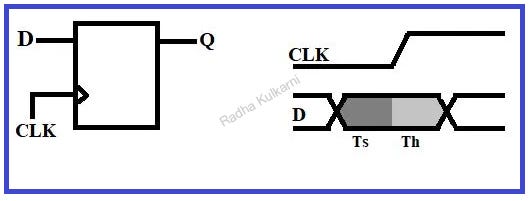
Let us consider an example of flip flop to understand setup time and hold time and why they are important in understanding metastability.

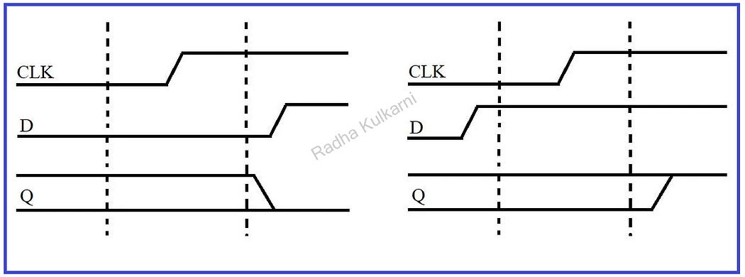
  1. Consider a D flip flop as shown in the above diagram. Here, input D is given to the flip flop, Q is the output, and clk is the clock cycle.
  2. In the waveform shown above, region one is the setup time region and region two is the hold time region.
  3. The setup time is the interval before the clock where the data must be held stable for the data to be latched correctly. Similarly, hold time is the interval after the clock where the data must be held stable.
  4. Here, the input D must remain stable and not change in the setup time before the clock occurs and it must also remain stable after the clock edge has occurred in region two i.e., during hold time.
  5. Aperture time can be defined as the total interval where input must remain stable which is setup time + hold time hence the flip flop must be stable during its aperture time.

- But why should it remain stable?

To understand this, we will consider 3 states as follow:

1] Consider that the input of the flip flop is stable for low value during aperture time. Then the output will take a low value.
2] Similarly, if the input of the flip flop is high in the aperture time, then the output will take a high value. This can be seen in the below diagram:

3] But if the input of the flip flop changes to a high or low value during the aperture time then the flip flop captures a value partway between low and high and this state is called the Metastable state or Quasi-stable state. This can be summarized in the below diagram.

The output will eventually take a high or a low value, but it will unlimited amount of time to settle or resolve to a good high or low value.

This process of flip-flop going into a metastable state and then getting into a high or a low state is called Metastability.

- Significance in VLSI Design:

Understanding setup time and hold time is crucial in VLSI design for several reasons:

  1. Timing Violations: Violating setup or hold time constraints can result in timing violations, leading to unreliable circuit operation and potential malfunctions.
  2. Metastability: Insufficient setup and hold times can cause metastability, where the flip-flop enters an unstable state, potentially resulting in incorrect output values.
  3. Clock Skew: Setup and hold times are affected by clock skew, which is the variation in arrival times of the clock signal at different parts of the circuit. Managing clock skew is essential to ensure proper setup and hold times are met.
  4. Performance and Reliability: Meeting setup and hold time requirements improves the overall performance and reliability of digital circuits, especially in high-speed designs.

Best Practices for Setup and Hold Time:

  1. Timing Analysis: Perform detailed timing analysis using EDA (Electronic Design Automation) tools to ensure that setup and hold time requirements are met under various operating conditions and corner cases.
  2. Clock Domain Crossing (CDC) Analysis: Pay special attention to signals crossing between different clock domains to prevent setup and hold time violations due to asynchronous interactions.
  3. Margin Consideration: Provide sufficient margin for setup and hold times to account for process variations, temperature changes, and voltage fluctuations, ensuring robust circuit operation across different conditions.

- Conclusion:

Setup time and hold time are critical concepts in VLSI design, ensuring the reliable and accurate operation of digital circuits. By understanding these timing parameters, engineers can design high-performance, robust, and error-free VLSI systems. Incorporating best practices, thorough timing analysis, and careful consideration of clock domains are key to meeting setup and hold time requirements effectively.

Like, Share and follow me if you like my content.
Thank You!

December 12, 2023

Diving into Sequential Circuits: Part 4— Registers


  • Flip flops are capable of storing 1-bit data, but to store more than 1 bit, registers are required. Registers, which are groups of flip flops, are employed to increase storage capacity. With n flip flops, it is possible to store an n-bit word using a single register.
  • Binary data stored in registers can be shifted between flip flops using shift registers.
  • A Shift Register is a group of flip flops used to store multiple bits of data and move the data from one flip flop to another. This shifting of data is accomplished using a clock signal. An n-bit shift register requires n flip flops. Shifting can occur either left or right using a Shift Left Register or Shift Right Register.
  • Shift registers are classified into the following types:
  1. SISO (Serial In Serial Out)
  2. SIPO (Serial In Parallel Out)
  3. PISO (Parallel In Serial Out)
  4. PIPO (Parallel In Parallel Out)
  5. Bi-directional Shift Register
  6. Universal Shift Register

To gain a deeper understanding of each register, simply click on the corresponding register. Happy Learning!!

September 29, 2023

Step-by-step guide on how to design and implement Flip Flops with testbench code on Xilinx Vivado design tool.

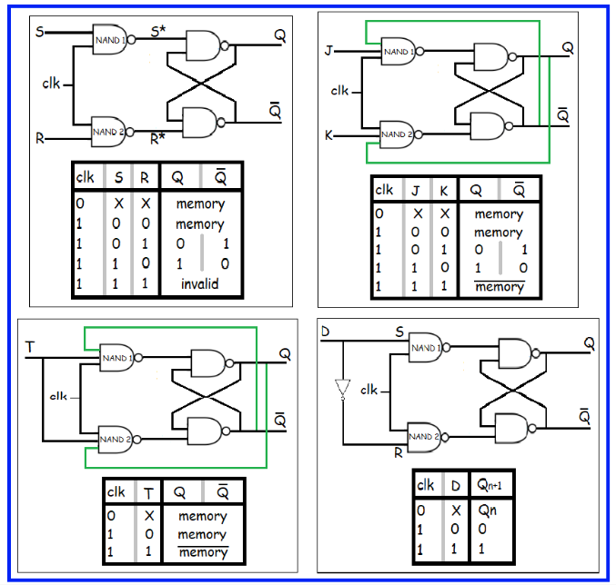
 In this project we will see how to implement all flip flops with testbench code on Xilinx Vivado design tool. Below diagram shows all flip flops along with there truth tables. To learn about how flip flops work in detail visit my blog: Diving into Sequential Circuits: Part 2 - Flip Flops 

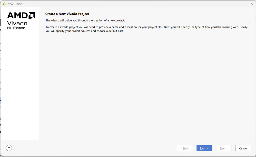
Step 1: Click on New Project -> Next

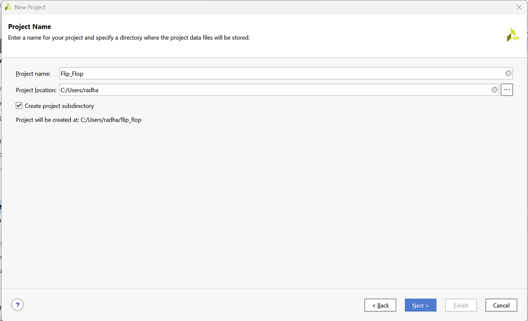
Step 2: Enter Project Name and Select appropriate Project Location -> Next

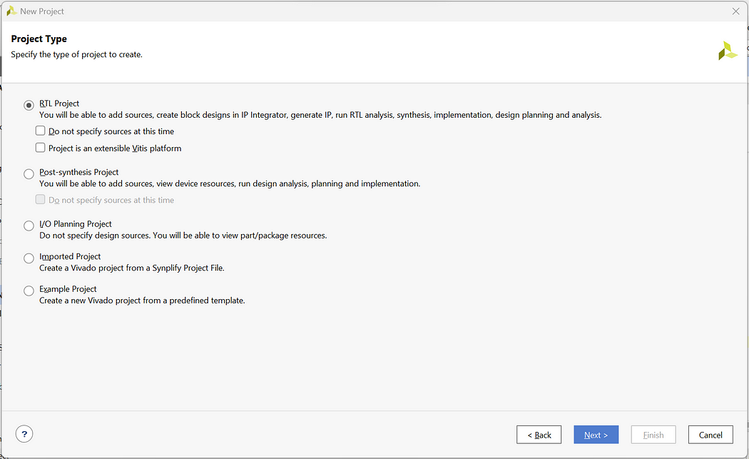
Step 3: Select RTL Project -> Next

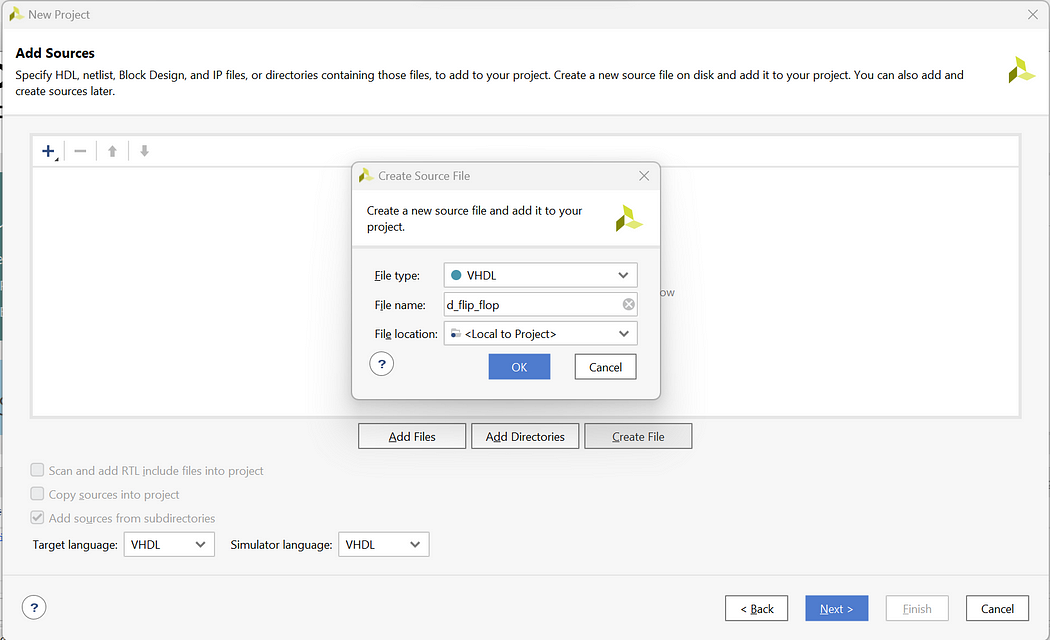
Step 4: Click on Create File and create file with file name d_flip_flop -> Next

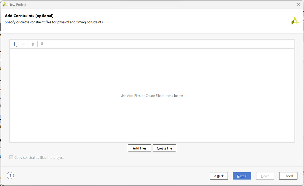
Step 5: We will not add the Constraint file So click on Next

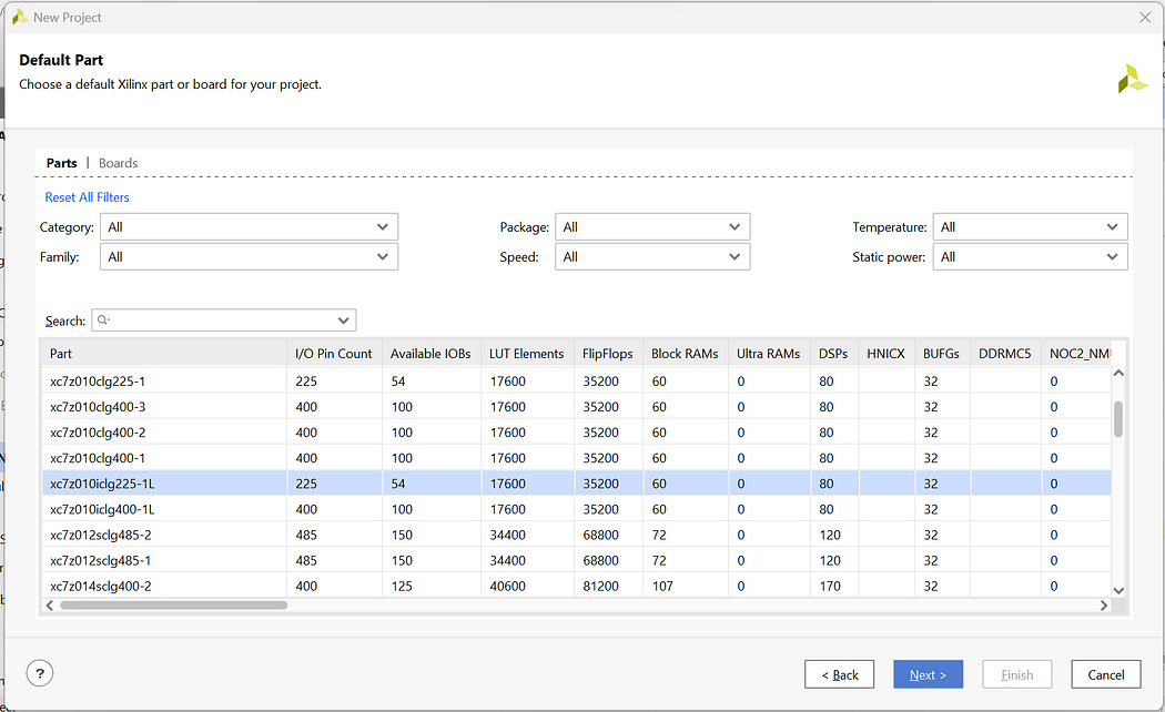
Step 6: For Default Part click on Next as we are not using any development Board

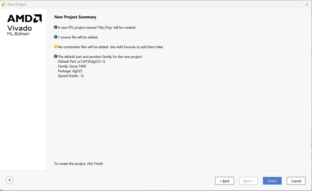
Step 7: Check the New Project Summary and click on Finish

Step 8: Now you will be prompted with the Define module page but we will create the complete code from scratch so click on cancel and Yes

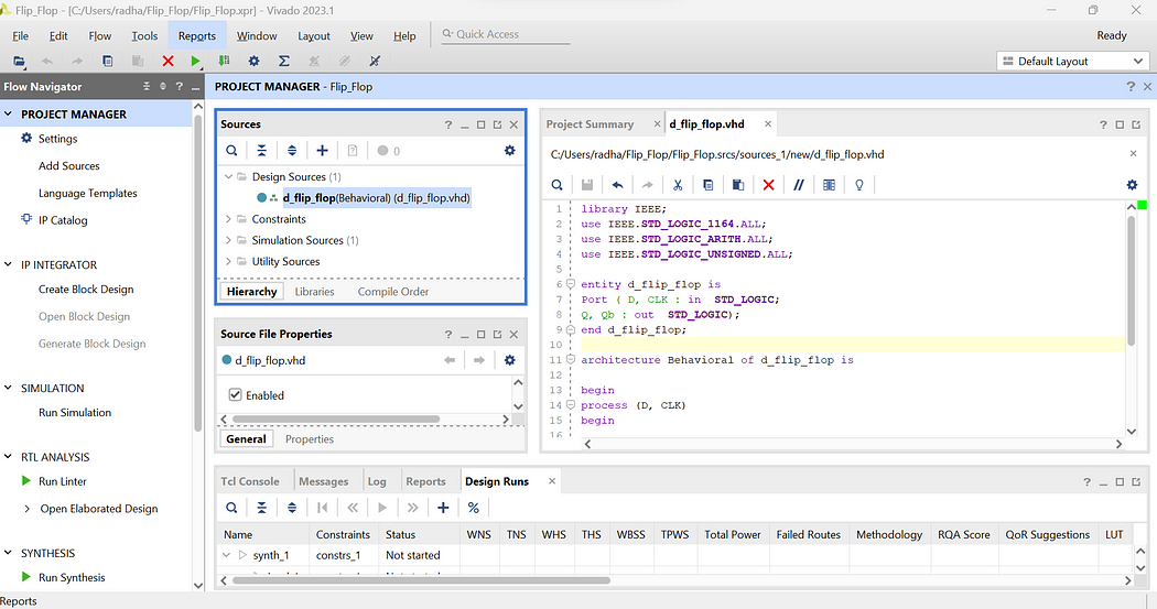
Step 9: Now on the Home Page click on Sources -> Design Sources -> Non-module Files

Step 10: Enter the below codes in the “d_flip_flop.vhd” files

library IEEE;
use IEEE.STD_LOGIC_1164.ALL;
use IEEE.STD_LOGIC_ARITH.ALL;
use IEEE.STD_LOGIC_UNSIGNED.ALL;

entity d_flip_flop is
Port ( D, CLK : in STD_LOGIC;
Q, Qb : out STD_LOGIC);
end d_flip_flop;

architecture Behavioral of d_flip_flop is

begin
process (D, CLK)
begin

if (rising_edge(CLK)) then
Q <= D;
Qb <= not D;

end if;
end process;
end Behavioral;

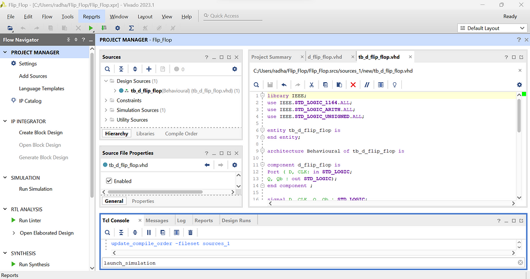
Step 11: Now to write the testbench code for and gate right click on Design Sources -> Add Sources -> Add or create design sources -> Create File -> Add File name as tb_d_flip_flop -> Finish -> Ok -> Yes

Step 12: Now open the testbench file and enter the below testbench code

library IEEE;
use IEEE.STD_LOGIC_1164.ALL;
use IEEE.STD_LOGIC_ARITH.ALL;
use IEEE.STD_LOGIC_UNSIGNED.ALL;

entity tb_d_flip_flop is
end entity;

architecture Behavioural of tb_d_flip_flop is

component d_flip_flop is
Port ( D, CLK: in STD_LOGIC;
Q, Qb : out STD_LOGIC);
end component ;

signal D, CLK, Q, Qb : STD_LOGIC;

begin
uut: d_flip_flop port map(
D => D,
CLK => CLK,
Q => Q,
Qb => Qb);

Clock : process
begin
CLK <= ‘1’;
wait for 10 ns;
CLK <= ‘0’;
wait for 10 ns;
end process;

stim : process
begin

D <= ‘0’;
wait for 40 ns;
D <= ‘1’;
wait for 40 ns;

end process;
end Behavioural;

Here, in testbench code we do not define values in entity hence we have kept it empty. Then in architecture we have copied the components of d_flip_flop and defined signals for connecting the ports of flip flop. Inside the process statement we write all 2 test cases from truth table and define the respective delays.

Step 13: Now as we have written all the codes let’s launch the simulation. Enter launch_simulation in the Tcl Console and press Enter

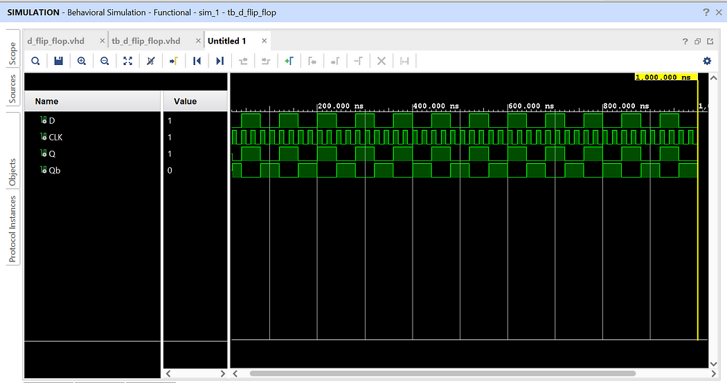
We have successfully implemented d flip flop with testbench code. Click on Zoom Fit to see the output waveform more clearly and verify the outputs.


If you want to implement other Flip Flops then the process would be same except the VHDL codes. Visit below links to see how to implement other Flip Flops: 


In this way, we can implement all Flip Flops using testbench codes.

Like, Share, and Follow me if you like my content.
Thank You


Explore Our Topics!

Check out the extensive list of topics we discuss:  Communication Protocols: -  USB   - RS232   -  Ethernet   -  AMBA Protocol: APB, AHB and...