Showing posts with label Communication protocols. Show all posts

January 4, 2025

Explore Our Topics!

Check out the extensive list of topics we discuss: 

  1. Communication Protocols:
    USB 
    - RS232 
    Ethernet 
    AMBA Protocol: APB, AHB and ASB 
    UART, I2C AND SPI
  2. Important concepts in VLSI:
    Designing a Chip? Here Are the 12 Important Concepts You Need to Know
    Metastability 
    - Setup time and Hold time
    Signal Integrity and Crosstalk effect
    Skews and Slack 
    Antenna Effect
  3. Semiconductor Memories
  4. Analog vs Digital Electronics
  5. Most Frequently Asked Questions in VLSI
  6. Transistors:
    BJT
    JFET
    MOSFET
    CMOS
    Transmission Gate CMOS
    Dynamic CMOS
  7. Sequential Circuits:
    Registers
    Counters
    Latches
    Flip Flops
  8. FPGA:
    ASIC vs FPGA
    FPGA Insights: From Concept to Configuration
    Full-Custom and Semi-Custom VLSI Designs: Pros, Cons and differences
    From Theory to Practice: CMOS Logic Circuit Design Rules Made Easy with Examples
  9. CMOS Fabrication:
    CMOS Fabrication
    Twin-Tub CMOS Technology
  10. Combinational Circuits
    - Logic Gates 
    - Boolean Algebra and DeMorgan's Law 
    - Multiplexer (MUX) and Demultiplexer (DEMUX) 
    - Half Adder
    - Full Adder
    - Half Subtractor
    - Full Subtractor
    - Encoders
    - Decoder
  11. Analog Electronics
    - OPAMP
    - Inverting and Non-inverting Amplifiers
    - Characteristics of OPAMP
    - OPAMP Application: Adder, Subtractor, Differentiator, and More!  
    - Filters
  12. Verilog
    - Verilog Datatypes
    - Comments, Numeral Formats and Operators
    - Modules and Ports
    - assign, always and initial keywords
    Blocking and Non-Blocking Assignments
    - Conditional Statements
    - Looping Statements
    - break and continue Statement
    - Tasks and Functions
    - Parameter and generate
    - Verilog Codes
  13. System Verilog: 
    Disable fork and Wait fork.
    Fork and Join.
  14. Project on Intel Quartus Prime and Modelsim:
    Vending Machine Controller
  15. Xilinx Vivado Projects
    1)VHDL
    Counters using Testbench code
    Flip Flops using Testbench code
    Logic Gates using Testbench code
    Full Adder using Half Adder and Testbench code
    Half Adder using Testbench code
    2)Verilog
    Logic Gates using Testbench code
    Counters using Testbench code
    Full Adder using Half Adder and Testbench code
    Half Adder using Testbench code
  16. VLSI Design Flow:
    Design Flow in VLSI
    Y chart or Gajski Kuhn Chart
  17. Projects on esim:
    Step-by-Step guide on how to Design and Implement a Full Adder using CMOS and sky130nm PDK
    Step-by-Step guide on how to Design and Implement a Half Adder using CMOS and sky130nm PDK
    Step-by-Step guide on how to Design and Implement a 2:1 MUX using CMOS and sky130nm PDK
    Step-by-Step guide on how to Design and Implement a Mixed-Signal Circuit of 2:1 Multiplexer
  18. IoT based project:
    Arduino
    Step-by-Step guide on how to Interface Load Cell using Arduino
  19. Kmaps:
    Simplifying Boolean Equations with Karnaugh Maps - Part:2 Implicants, Prime Implicants and Essential Prime Implicants. 
    Simplifying Boolean Equations with Karnaugh Maps - Part:1 Grouping Rules.
    Simplifying Boolean Equation with Karnaugh Maps.

November 27, 2023

Ethernet Essentials: A Deep Dive into Networking Fundamentals


  • Ethernet is a widely used networking technology employed for sharing data and facilitating communication among devices within a Local Area Network (LAN). It adheres to the IEEE standard 802.3 and typically employs a Bus topology.

  • Utilizing the CSMA/CD (Carrier Sense Multiple Access/Collision Detection) media access control method, Ethernet employs the Manchester Encoding technique.
  • Various types of Ethernet networks exist for connecting devices and transferring data, including:
  1. Fast Ethernet: Transfers data at a speed of approximately 100 Mbps.
  2. Gigabit Ethernet: Transfers data at a speed of 1 Gbps.
  3. 10 Gigabit Ethernet: Transfers data at a speed of 10 Gbps.
  • To understand how Ethernet functions, let’s examine its frame format, which comprises the following seven parts:
  • Below diagram shows Ethernet Frame format:

  1. Preamble
  2. SFD (Start Frame Delimiter)
  3. DA (Destination Address)
  4. SA (Source Address)
  5. Length
  6. Data
  7. CRC (Cyclic Redundancy Check)
  • Breaking down each part:
  1. The frame format initiates with the Preamble and SFD, both operating at the physical layer.
  2. Preamble: A 7-byte block featuring an alternating pattern of 0’s and 1’s (101010…10)which basically indicate the starting of the frame and is used for synchronization between sender and receiver.
  3. SFD (Start Frame Delimiter): A 1-byte field always set to 10101011. The 1 at last is used to break the bit pattern and indicate the start of actual frame.
  4. The DA, SA, and Length fall under the Data Link Layer.
  5. DA (Destination Address): A 6-byte field containing the destination address.
  6. SA (Source Address): A 6-byte field containing the source address, considering MAC addresses.
  7. Length: A 2-byte (16-bit) field indicating the length of the entire Ethernet frame.
  8. Data: The Data, also known as Payload, is where the actual data is inserted. The minimum data size is 46 bytes, resulting in a frame size from DA to CRC of 64 bytes. The maximum data that can be sent in one frame is 1500 bytes.
  9. CRC (Cyclic Redundancy Check): A 4-byte field containing a 32-bit hash code of data created using the destination address, source address, length, and data fields. This checksum is used for detecting corrupted data in the entire frame. Data is considered damaged or corrupted if the calculated checksum at the destination differs from the supplied checksum value.

In this way, the Ethernet communication protocol works.

Do explore my other blogs covering the following communication protocols:

  1. AMBA, APB, AHB and ASB
  2. UART, I2C, and SPI

Like, Share and Follow me if you like my content.
Thank You.

November 15, 2023

Inside the USB: Mastering USB Protocol for Tech Enthusiasts

 USB, which stands for Universal Serial Bus, is an asynchronous communication protocol enabling data exchange and power transfer among electronic devices. Originally developed by Compaq, DEC, IBM, Intel, Microsoft, NEC, and Nortel, USB aims to standardize the connection of peripherals, such as mice, keyboards, printers, etc., to computer systems.

  • The different types of USB versions are as follows:
  • USB connectors come in various shapes and sizes, each designed for specific purposes. Here are some common types of USB connectors:
  1. USB Type-A
  2. USB Type-B
  3. USB Type-C
  4. USB Mini
  5. USB Micro
  6. USB 3.0
  • Working:
  1. USB operates with a host-slave architecture, where the computer acts as the host or master, and connected peripherals are slaves.
  2. It supports up to 127 devices due to its 7-bit addressing.
  3. USB is asynchronous, eliminating the need for a clock signal.
  4. Here, host can only initiate the Data transfer.
  5. Now to understand the working let us consider USB type A and USB type B.
  6. Below digaram shows internal pins of Type A and Type B USB.

The USB connector features four pins (1, 2, 3, 4), with Pin 1 and Pin 4 designated for Vcc (power supply) and Gnd (ground), while Pin 2 and Pin 3 carry D- (data negative) and D+ (data positive) signals. The D+ and D- signals convey the same data, albeit in a mirrored fashion. At the receiver side, a differential amplifier calculates the disparity between D+ and D-, providing a robust mechanism for noise immunity.

USB devices boast hot swapping and plug-and-play capabilities. Hot swapping enables users to connect or disconnect devices while the system is operational, while plug and play ensures that the operating system autonomously identifies and configures connected devices, eliminating the need for manual intervention. The processor continuously monitors the state of I/O devices to facilitate seamless data transmission, relieving I/O devices from the responsibility of updating the processor.

When a new I/O device connects to the hub, it is assigned the address ‘0.’ Subsequently, when the host establishes a connection with the new device, it assesses the device’s capabilities and selects a suitable driver for communication. This dynamic process ensures efficient and tailored communication between the host and the connected I/O devices.

  • USB Architecture:

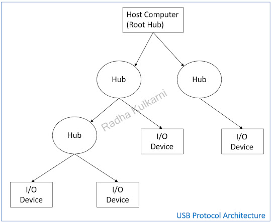
The diagram below illustrates the architecture of the USB protocol, which operates on a Tree Topology.

In this configuration, a single host serves as the central point, and multiple slave devices can be connected to it. I/O devices establish connections with the computer through a Hub, creating a tree-like structure. The Hub functions as the nexus for connecting both I/O devices and the computer, facilitating an organized and efficient network topology.

  • USB data format:

In USB communication, data is transferred in the form of packets, categorized into four main types: Token, Data, Handshake, and Start of Frame. To facilitate effective data transmission, USB adheres to a specific message format outlined below:


  1. SYNC: Every USB packet initiates with a SYNC field, an 8-bit segment utilized for synchronizing the transmitter and receiver to facilitate data transmission.
  2. Packet Identifier Field (PID): The PID field within the USB protocol serves to identify the type of packet being transmitted. This 8-bit field consists of upper 4 bits indicating the packet type and lower 4 bits representing the bitwise complement of the upper 4 bits.
  3. Address Field: The address field specifies the address of the USB device involved in the communication. Each USB device connected to a bus is assigned a unique address. The 7-bit address field in a token packet allows for up to 127 unique device addresses.
  4. Endpoint Field: The endpoint field directs data transfers to and from specific endpoints on a USB device, identified by their endpoint numbers. This 4-bit field in a token packet represents up to 16 different endpoints (0 to 15), with endpoint 0 reserved for configuration, status, and control operations. Additionally, the endpoint field indicates the direction of data transfer — host to device or device to host.
  5. Data Field: The data field carries the actual information being transferred between the USB host (typically a computer) and the USB device. The length of the data field is not fixed and ranges from 0 to 8192 bits.
  6. CRC (Cyclic Redundancy Check): CRC is an error-checking mechanism crucial for ensuring the integrity of transmitted data in the USB protocol. It assists the receiver in verifying that the received data matches the original data sent by the transmitting end.
  7. EOP field: The End of Packet (EOP) field is used to indicate the conclusion of a packet and prepares for the start of the next one, ensuring a well-defined boundary between successive packets.
  • Applications of USB Protocol:
  1. Computer Peripherals: USB is extensively used for connecting a diverse range of computer peripherals, including keyboards, mice, printers, scanners, webcams, and external hard drives.
  2. Storage: Many hard drives leverage the USB protocol for efficient data transfer, storage, and transportation.
  3. Smartphones: USB is a key technology for smartphones, serving dual purposes for charging and data transfer between mobile devices and other peripherals.
  4. Cameras and Webcams: Cameras, webcams, and video streaming devices utilize USB for data transfer and control. USB connections provide a reliable means for transferring multimedia content and enabling communication between imaging devices and computers.
  5. Gaming Peripherals: USB is commonly employed for connecting gaming peripherals such as controllers, joysticks, and other input devices.
  6. Industries: USB finds applications in industrial settings, particularly in the connection of sensors, actuators, and other industrial equipment. Its standardized interface simplifies integration and communication in diverse industrial applications.
  7. Medical Devices: USB is utilized in the medical field to connect various medical devices to computers for data transfer and communication. It ensures a reliable and standardized interface for exchanging data between medical equipment and computer systems, facilitating healthcare operations.

Do explore my other blogs covering the following communication protocols:

  1. AMBA, APB, AHB and ASB
  2. UART, I2C, and SPI
  3. Ethernet

Like, Share and Follow me if you like my content.
Thank You.

June 18, 2023

Understanding the AMBA Protocol: APB, AHB, and ASB Explained

  • AMBA stands for Advanced Microcontroller Bus Architecture.
  • What is a Microcontroller ??
    A microcontroller is a small computer on a single VLSI integrated circuit (IC) chip. It comprises one or more CPUs (processor cores), as well as memory and programmable input/output peripherals. To facilitate communication between these internal components, a bus architecture is required. A Bus architecture includes system bus which is address bus + data bus +control bus.
  • Possible functional blocks on Board:
    1. One or more Microcontroller/ microprocessor.
    2. Memory — SRAM, DRAM, EPROM, Flash Memory.
    3. DSP — Digital Signal Processor.
    4. DMA — Direct Memory Access.
    5. USBs, SPI, I2C, IO ports, ADC/DAC, Timer.

    Now to interface all these functional blocks we need AMBA. AMBA is a System-on-Chip (SoC) bus architecture commonly used in microcontrollers.

    • Definition of AMBA:
      The ARM Advanced Microcontroller Bus Architecture (AMBA) is an open standard on-chip interconnect specification for connecting and managing functional blocks in a System-on-a-Chip (SoC). Developed by ARM, the AMBA specification has become the de facto standard for interfacing components within an SoC.
    • Essentially, the AMBA protocols define how functional blocks communicate with each other. They are used to minimize the silicon infrastructure, support modular system designs, and ensure system technology independence. AMBA protocols are widely used in a range of ASIC and SoC parts, including applications processors found in devices such as IoT devices, smartphones, and networking SoCs.
    • AMBA Standards:
    1. AHB: Advanced High Performance Bus
    2. ASB: Advanced System Bus
    3. APB: Advanced Peripheral Bus
    4. ATB: Advanced Trace Bus
    5. AXI: AMBA Extensible Interface
    • The diagram below illustrates the AMBA (Advanced Microcontroller Bus Architecture) bus, consisting of the AHB (Advanced High-Performance Bus) and ASB (Advanced System Bus), as well as the APB (Advanced Peripheral Bus):
    1. In the diagram, the AHB/ASB is designed to handle high-performance and high-bandwidth modules or interfaces, including components such as memory, ARM (Advanced RISC Machines) processors, and DMA (Direct Memory Access) controllers.
    2. On the other hand, the APB is intended for low-bandwidth modules such as UART (Universal Asynchronous Receiver-Transmitter), Timer, Keypad, and PIO (Programmable Input/Output).
    3. To establish communication between these high and low bandwidth buses, a bridge is employed.
    4. The bridge serves as an intermediary, facilitating data transfer and control signals between the AHB/ASB and APB buses. This allows seamless integration of both high-performance and low-bandwidth modules within a larger system.
    • APB:
    1. The Advanced Peripheral Bus (APB) is utilized for low-bandwidth peripherals.
    2. It facilitates the reading and writing of data between the bridge and the peripherals.
    3. In the architecture, the bridge functions as the master, while all the peripherals act as slaves.
    4. The APB employs the same signals for both read and write operations.
    5. It does not support burst transfers.
    • Following are the different versions of AMBA APB with each having slight increased features than the previous:
    1. AMBA 2 APB : Basic read and write
    2. AMBA 3 APB : wait transfer and error response
    3. AMBA 4 APB : transaction protection and sparse data transfer.
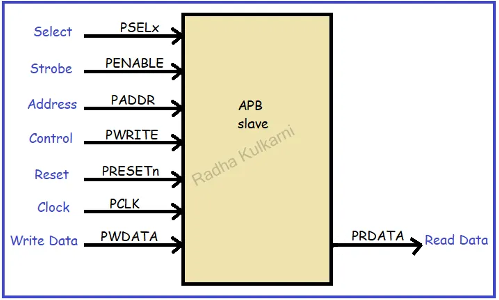
    • The diagram below illustrates the signal description of the Advanced Peripheral Bus (APB) and its associated signals:
    1. PSELx: Slave selection signal, where ‘x’ represents the number of slaves.
      The maximum width of signals in the APB is 32 bits.
    2. PCLK: Clock signal.
    3. PRESETn: Reset signal.
    4. PADDR and PWRITE: Address and control signals used to determine whether a read or write operation should be performed on the bus. Typically, a value of 1 indicates a write operation, while 0 indicates a read operation. The address signal indicates the specific location or register to be accessed.
    5. PENABLE: Indicates when the access should occur.
    6. PWDATA and PRDATA: Data buses with a width of 32 bits, used for transferring data during read and write operations, respectively.
    • Operation:

      APB has three operating states:
    1. idle
    2. Setup
    3. Access state

    The diagram below depicts the Finite State Machine (FSM) of the three states in the Advanced Peripheral Bus (APB):

    1. IDLE: This is the default state of the APB. When a reset occurs, the bus enters the IDLE state. In this state, the enable signal is set to 0, and no slave is selected, resulting in no data transfer.
    2. SETUP: In the SETUP state, the slave to be selected for communication is determined. The corresponding PSELx signal is set to 1, while PENABLE remains at 0, indicating that the data transaction has not yet begun. When a transfer is required, the bus transitions to the SETUP state. During this phase, the bus waits for one clock cycle before moving to the ACCESS phase.
    3. ACCESS: In the ACCESS state, the PENABLE signal is set to high. The address, write_e, select, and write data signals must remain stable during the transition from the SETUP to ACCESS state. The ACCESS state is controlled by the PREADY signal. If PREADY is low (0), the bus remains in the same phase. If PREADY is high (1) and no data transfer is involved, the bus returns to the IDLE state. If a data transfer is required, the bus transitions back to the SETUP state for the next transaction. Based on the PWRITE control signal, data is either read from or written to the bus in this state. Any change in the PWRITE signal during this transition can result in data loss.
    • Timing diagram:

    The diagram below illustrates the timing diagram for an APB (Advanced Peripheral Bus) Write transfer with no wait state:

    In the diagram:
    The period from T0 to T1 represents the IDLE state, during which no data transaction occurs, and both the PSEL and PENABLE signals are low.
    From T1 to T2, we enter the SETUP state where the address for the register is checked, and the decision to read or write data is made based on the PWRITE control signal. In this case, the PWRITE signal is set to 1, indicating a write operation, and we also check the PSEL signal. The SETUP state is entered only when PSEL is high. At this stage, PENABLE is still set to 0.

    The period from T2 to T3 corresponds to the ACCESS state. Here, we set PENABLE to 1 and pay attention to the PREADY signal. The data from DATA1 will be stored or written in ADDR1 only when both the PENABLE and PREADY signals are 1.

    Now, let’s consider the diagram for a Write transfer with a wait state:

    In this diagram, the transactions are similar to the previous one, with T0 to T1 representing the IDLE state, T1 to T2 as the SETUP state, and T2 to T3 as the ACCESS state. The difference lies in the ACCESS state, where data transitions only when the PREADY signal is 1. However, in this case, the PREADY signal is low (0), indicating that no data transition occurs between T2 and T3. Therefore, T3 to T4 becomes an extended ACCESS state where we wait for the PREADY signal to become high. This period, during which the ACCESS state is extended while waiting for the PREADY signal to transition the data from DATA1 to ADDR1, is referred to as a wait state transfer. Subsequently, between T4 and T5, the PREADY signal becomes 1, and the ACCESS state proceeds to transition the data, completing the operation within this period.

    • AHB and ASB:
    1. The Advanced High-Performance Bus (AHB) or Advanced System Bus is designed for interfaces requiring high bandwidth and high clock frequencies.
    2. It provides an efficient connection for processors, on-chip memories, and off-chip external memory interfaces.
    3. The AHB supports the concepts of multiple masters and multiple slaves, allowing for complex system configurations.
    4. Burst transfers are supported, enabling efficient data transfer in blocks.
    5. The AHB introduces several new features, including split transactions, single-cycle bus master handovers, single-clock-edge operation, and wider data bus configurations.
    6. The diagram below depicts the AHB protocol and its various components, including masters, slaves, address and control multiplexers, a read multiplexer, a write multiplexer, an arbiter, and a decoder.

    In the AHB (Advanced High-Performance Bus) architecture, there are 3 masters connected to 4 slaves. The HADDR bus is responsible for slave selection, allowing the masters to specify the target slave’s address. The HWDATA bus is used to transfer write data from the master to the selected slave, while the HRDATA bus is used for read data transfer from the slave back to the master.

    To gain control of the bus and initiate a data transfer, a master sends a request to the arbiter. The arbiter grants access based on a prioritization scheme, ensuring that masters with higher priority are given access first. The decoder receives the address signal from the master and decodes it, generating slave select signals to identify the intended recipient. The slave responds to the master using the HRESP signal. Once the transfer is initiated, data is exchanged between the master and the slave. Additionally, there are other AHB signals employed, such as HCLK (the clock signal for the bus), HRESET (reset signal), HSELx (slave select signals for each slave), and HREADY (a signal indicating the readiness of the slave to accept data).

    On the other hand, the ASB (Advanced System Bus) is a simplified version of the AHB, specifically designed for 16-bit and 32-bit systems. The ASB operates similarly to the AHB, starting with a master requesting access to the bus from the arbiter. Once the arbiter grants the request, the data transfer begins. The decoder decodes the address placed on the bus and selects the appropriate slave. The slave responds to the master, and the actual data transfer takes place. In the ASB, various signals are utilized, including BCLK (bus clock signal), BnRes (bus reset signal), BTRAN (transfer acknowledge signal), BWRITE (write signal), BERROR (error signal), and DSELx (slave select signals for each slave), among others.

    A high performance and low performance bus cannot be connected directly. So, a compatible bridge such as AHB-APB or ASB-APB bus can be used.

    • The two main characteristics of bus interface performances are:
    1. Bandwidth: It is the rate at which data can be driven across the interface. or can also be f=defined as number of bytes that can be transferred per second.
    2. Latency: This is the delay between start and end of the data transfer. or can be defined as how long does it take for data to go from memory to processor.

    The efficiency of your interface will depend on the extent to which it achieves the maximum bandwidth and zero latency.

    Number of devices to be connected to the bus can also de one of the characteristics.

    • Uses of AMBA:

    There are several significant benefits to using the AMBA (Advanced Microcontroller Bus Architecture) standard. These benefits include:

    1. Efficient IP Reuse: AMBA facilitates the reuse of intellectual property (IP), allowing designers to leverage pre-existing modules and designs. This capability reduces development costs and shortens project timescales, as designers can incorporate proven components into their systems rather than developing everything from scratch.
    2. Compatibility and Flexibility: AMBA is a widely adopted standard, making it highly compatible with a variety of System-on-Chip (SoC) designs. It provides a flexible framework for connecting various components, allowing designers to seamlessly integrate different IP blocks from different vendors into a cohesive system.
    3. Scalability: AMBA supports different bus protocols, such as AMBA 5 AHB (Advanced High-Performance Bus) and AMBA 5 AXI (Advanced eXtensible Interface). This scalability enables designers to choose the appropriate bus protocol based on their specific requirements, ensuring optimal performance and resource utilization.
    4. Silicon Infrastructure Optimization: AMBA helps minimize silicon infrastructure requirements by providing efficient on-chip communication capabilities. It offers protocols and mechanisms for high-performance and low-power communication between IP modules, reducing the overall area and power consumption of the chip.
    5. Ecosystem Support: The popularity of AMBA has led to the development of a rich ecosystem of tools, IP blocks, and design methodologies. This ecosystem provides designers with a wide range of options and resources, enhancing productivity and enabling faster development cycles.

    In summary, the AMBA standard offers benefits such as efficient IP reuse, compatibility and flexibility, scalability, optimization of silicon infrastructure, and a supportive ecosystem. These advantages contribute to reduced development costs, shorter timescales, and improved performance in SoC designs.

    Like, Share and Follow me if you like my content.
    Thank You.

Explore Our Topics!

Check out the extensive list of topics we discuss:  Communication Protocols: -  USB   - RS232   -  Ethernet   -  AMBA Protocol: APB, AHB and...