Showing posts with label multiplexer. Show all posts

September 2, 2024

Mastering Verilog: Part 10 — Understanding parameter and generate Constructs

When working with Verilog, two constructs that can greatly enhance the flexibility and reusability of your code are parameter and generate. These constructs allow you to create more modular and adaptable designs. In this blog, we’ll delve into how these features work and how you can use them effectively in your Verilog code.

Understanding parameter in Verilog

The parameter keyword in Verilog is used to define constants that can be used throughout your module. Parameters allow you to make your design more flexible by allowing you to modify the behavior of your module through parameterization rather than hardcoding values.

  • Why Use Parameters?
  1. Flexibility: Parameters allow you to easily change values without modifying the core module code.
  2. Reusability: You can create more generic and reusable modules by adjusting parameters.
  3. Readability: Using parameters can make your code more readable and maintainable.
  • How to Define and Use Parameters
    To define a parameter, use the following syntax:
module my_module #(parameter WIDTH = 8, parameter DEPTH = 16) (
input [WIDTH-1:0] data_in,
output [WIDTH-1:0] data_out
);
// Module implementation
endmodule

In this example, WIDTH and DEPTH are parameters with default values of 8 and 16, respectively. You can override these default values when you instantiate the module:

my_module #(.WIDTH(16), .DEPTH(32)) instance1 (
.data_in(data_in_16),
.data_out(data_out_16)
);

Example: Parameterized Adder

Objective: Create a simple parameterized adder module that can be configured for different bit-widths.
Code:

module adder #(parameter WIDTH = 8) (
input [WIDTH-1:0] a,
input [WIDTH-1:0] b,
output [WIDTH-1:0] sum,
output carry_out
);
assign {carry_out, sum} = a + b;
endmodule

Explanation:

  1. parameter WIDTH = 8: This parameter allows you to specify the width of the adder. The default value is 8 bits.
  2. input [WIDTH-1:0] a, b: Inputs a and b are vectors with a width specified by the WIDTH parameter.
  3. output [WIDTH-1:0] sum: The output sum has the same width as the inputs.
  4. assign {carry_out, sum} = a + b: Adds a and b, assigning the sum and carry-out.

Instantiation:

adder #(.WIDTH(4)) adder_4bit (
.a(4'b1010),
.b(4'b0101),
.sum(sum_4bit),
.carry_out(carry_out_4bit)
);
adder #(.WIDTH(16)) adder_16bit (
.a(16'h1234),
.b(16'h5678),
.sum(sum_16bit),
.carry_out(carry_out_16bit)
);

This example creates two instances of the adder module: one with a 4-bit width and another with a 16-bit width.

Exploring generate in Verilog

The generate construct is used to create multiple instances of a module or logic based on a parameter or a condition. This can be particularly useful for generating repetitive structures such as arrays of registers or counters.

  • Why Use Generate?
  1. Code Reduction: Helps reduce repetitive code by allowing you to generate multiple instances or structures with a single block of code.
  2. Conditional Instantiation: Allows you to instantiate modules or logic conditionally based on parameters.
  • Basic Syntax of Generate
    The generate construct is used in conjunction with genvar and for loops to create multiple instances:
module generate_example #(parameter N = 4) (
input [N-1:0] in,
output [N-1:0] out
);
genvar i;
generate
for (i = 0; i < N; i = i + 1) begin : gen_block
assign out[i]
= in[i]; // Example: copying input to output
end
endgenerate
endmodule

In this example, the generate block creates N instances of the assign statement. The genvar keyword is used to declare a variable for use in the generate block.

Example: 2-to-1 Multiplexer Array

Objective: Use generate to create multiple instances of a 2-to-1 multiplexer.
Code:

module mux2to1 #(parameter WIDTH = 8) (
input [WIDTH-1:0] a,
input [WIDTH-1:0] b,
input sel,
output [WIDTH-1:0] y
);
assign y = sel ? b : a;
endmodule

module top_module #(parameter NUM_MUX = 4) (
input [NUM_MUX*8-1:0] data_in,
input [NUM_MUX-1:0] sel,
output [NUM_MUX*8-1:0] mux_out
);
genvar i;
generate
for (i = 0; i < NUM_MUX; i = i + 1) begin : mux_gen
mux2to1 #(.WIDTH(8)) mux_instance (
.a(data_in[i*8 +: 8]),
.b(data_in[(i+1)*8-1 -: 8]),
.sel(sel[i]),
.y(mux_out[i*8 +: 8])
);
end
endgenerate
endmodule

Explanation:

  1. mux2to1 Module: A parameterized 2-to-1 multiplexer with a configurable data width.
  2. top_module: Uses a generate block to create multiple instances of the mux2to1 module.
  3. genvar i: A generate variable used to iterate through the for loop.
    for (i = 0; i < NUM_MUX; i = i + 1): Loop generates NUM_MUX instances of mux2to1.
  4. data_in[i*8 +: 8]: Extracts an 8-bit segment from data_in for the a input.
  5. mux_out[i*8 +: 8]: Collects the output from each multiplexer instance.

Instantiation:

top_module #(.NUM_MUX(4)) top_instance (
.data_in({32'hA5A5A5A5, 32'h5A5A5A5A, 32'hFFFF0000, 32'h0000FFFF}),
.sel(4'b1010),
.mux_out(mux_out)
);

In this example, top_instance creates a 4-way multiplexer where each instance of mux2to1 is configured to select between pairs of 8-bit inputs.

Conclusion

The parameter and generate constructs in Verilog provide powerful tools for creating flexible, reusable, and efficient designs. Parameters enable you to adjust module behavior and design size without modifying the core module, while the generate construct helps in managing repetitive structures and conditional instantiation.

By mastering these constructs, you can enhance the adaptability and maintainability of your Verilog code, making it more robust and scalable for complex designs.

June 7, 2024

Step-by-Step Guide to Multiplexers (MUX) and Demultiplexers (DEMUX) in Digital Engineering

 In digital electronics, the efficient handling of multiple data signals is paramount. Two critical components facilitating this task are the Multiplexer (MUX) and the Demultiplexer (DEMUX). These devices play a vital role in data routing, signal transmission, and resource optimization within digital systems. This blog delves into the concepts, functionalities, types, and applications of MUX and DEMUX, providing a comprehensive understanding of these essential components.

What is a Multiplexer (MUX)?

A multiplexer, commonly abbreviated as MUX, is a combinational circuit that selects one of several input signals and forwards the selected input to a single output line. The selection of the input signal is controlled by a set of selection lines. Essentially, a multiplexer acts as a data selector, accepting multiple input lines and providing a single output. Typically, a multiplexer has 2^n input lines and 1 output line, where n is the number of selection lines.

In digital logic, a multiplexer is a circuit capable of accepting several inputs and generating a single output based on the control signals provided by the selection lines. This makes the multiplexer a type of data selector, efficiently routing one of the many inputs to a single output line. The selection lines determine which input signal is switched to the output line, functioning as a multi-position switch that is digitally controlled.

Therefore, a multiplexer is designed to switch one of the many input lines to a single output line through the use of control signals. This functionality earns the multiplexer its alternative name, the “many-to-one” circuit. The select lines play a crucial role in determining which input signal will be transmitted to the output, making multiplexers indispensable in digital systems for data routing and signal selection.

The block diagram of a multiplexer is shown below:

How Does a MUX Work?

The operation of a MUX can be summarized in the following steps:

Inputs and Selection Lines: A MUX has multiple input lines but only one output line. The number of selection lines determines which input line is connected to the output. For example, a 2-to-1 MUX has 2 input lines, 1 output line, and 1 selection line.
Selection Logic: The selection line(s) are binary encoded, which means they can represent binary values (0, 1, etc.). Based on the binary value present at the selection line(s), the corresponding input line is connected to the output.
Output: The selected input line’s value is transmitted to the output.

Here’s an example of a 4:1 Multiplexer (MUX):

The block diagram of a 4:1 MUX has four input lines labeled I0,I1,I2,I3. two selection lines labeled S0,S1 and one output line labeled Y
The MUX selects one of the four input lines based on the combination of the selection lines and forwards it to the output line.
The gate-level diagram shows the implementation of the 4:1 MUX using logic gates:
Four AND gates are used, each connected to one of the inputs (I0,I1,I2,I3) and the appropriate combination of the selection lines and their inverses.
The outputs of the AND gates are connected to an OR gate, which combines them to produce the final output Y

What is a Demultiplexer (DEMUX)?

A demultiplexer, commonly abbreviated as DEMUX, is a combinational circuit that takes a single input and channels it to one of several output lines. The selection of the output line is controlled by a set of selection lines. As a data distributor, a demultiplexer distributes a single input signal across multiple outputs. In a typical demultiplexer, there is 1 input line and 2^n output lines, where n is the number of selection lines. This digital combinational circuit is designed to take one input signal and generate multiple output signals, effectively reversing the operation of a multiplexer.

A demultiplexer, by distributing a single input signal to multiple output lines, is also referred to as a type of data distributor. The operation of a demultiplexer is essential in applications that require a single source to connect to multiple destinations. For example, demultiplexers are widely used in arithmetic and logic units (ALUs), communication systems for data transmission, wavelength routers, and various other applications.

The block diagram of a Demultiplexer is shown below:

How Does a DEMUX Work?

The operation of a DEMUX can be summarized in the following steps:

Input and Selection Lines: A DEMUX has one input line, multiple output lines, and a set of selection lines.
Selection Logic: The selection lines determine which output line will receive the input signal. The binary value present at the selection lines decides the connection.
Output: The input signal is transmitted to the selected output line.

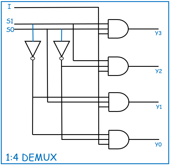
Here’s an example of a 1:4 Demultiplexer (DEMUX):

The block diagram of a 1:4 DEMUX has one input line labeled I two selection lines labeled S0 and S1 , and four output lines labeled ​Y0,Y1,Y2,Y3
The DEMUX takes the single input and distributes it to one of the four output lines based on the combination of the selection lines.
The gate-level diagram shows the implementation of the 1:4 DEMUX using logic gates:
Four AND gates are used, each connected to the input I and the appropriate combination of the selection lines and their inverses.
Each AND gate’s output is connected to one of the output lines Y0,Y1,Y2,Y3

Below are the differences between a multiplexer (MUX) and a demultiplexer (DEMUX):

Conclusion:

Multiplexers (MUX) and demultiplexers (DEMUX) are fundamental components in digital circuits, essential for efficient data routing and signal management. While a MUX selects one of many inputs and directs it to a single output, a DEMUX takes a single input and channels it to one of many outputs. These devices are crucial in various applications, from data selection and distribution to signal routing in communication systems. Understanding their operation, functionality, and differences is vital for anyone involved in digital electronics and system design, ensuring effective and optimized circuit implementations.

Explore Our Topics!

Check out the extensive list of topics we discuss:  Communication Protocols: -  USB   - RS232   -  Ethernet   -  AMBA Protocol: APB, AHB and...