Operational amplifiers (OPAMPs) are incredibly versatile components in analog electronics, offering a wide range of applications. Beyond their basic inverting and non-inverting configurations, OPAMPs can perform complex mathematical operations such as addition, subtraction, differentiation, and more. This chapter will explore these key applications, showing how OPAMPs serve as essential building blocks in signal processing and analog computation.
1] OPAMP as an Adder (Summing Amplifier)
One of the most practical applications of an OPAMP is as an adder (or summing amplifier). This circuit combines multiple input signals and outputs their sum, scaled by the feedback resistor network. The inverting and non-inverting configurations can both be used for this purpose.
Below is the diagram showing the OPAMP as a Summing Amplifier in the inverting configuration:

As shown in above figure, V1, V2, and V3 are three inputs fed to the inverting input through input resistors R1 , R2, and R3. Since the inverting input is at virtual ground, the three currents I1, I2 and I3 are given by:
I1=V1/R1
I2=V2/R2
I3=V3/R3
By Kirchhoff’s Current Law (KCL), the current through the feedback resistor Rf is equal to the sum of these input currents, but it flows in the opposite direction:
If = -Iin
(Vo/Rf) = -[I1+I2+I3]
Vo = -Rf[(V1/R1)+(V2/R2)+(V3/R3)]
This is the general formula for an inverting summing amplifier.
if R1=R2=R3 then
Vo = -(Rf/Rin)[V1+V2+V3]
if (Rf/Rin) = 1 then
Vo =-[V1+V2+V3]
This means the output is simply the inverted sum of the input voltages. In this way, an op-amp configured as an adder effectively combines multiple input signals into a single output, allowing for straightforward manipulation of complex signals. This configuration is essential in various applications, enabling efficient signal processing and integration in electronic circuits.
2] OPAMP as a Subtractor (Differential Amplifier)
An OPAMP can also be configured as a subtractor, allowing for the subtraction of one signal from another. This configuration is commonly used in applications where it’s necessary to compute the difference between two input signals, such as in sensor signal conditioning or instrumentation amplifiers.
The differential amplifier subtracts one input signal from another. The inverting input receives the negative signal, while the non-inverting input receives the positive signal. The output reflects the difference between these two inputs, scaled by the feedback and input resistors.
Below is a diagram showing the OPAMP as a Differential Amplifier:

In this subtractor circuit, V1 is connected to the inverting terminal through resistor R1, and V2 is connected to the non-inverting terminal via another R1. Resistor R2 is placed between the non-inverting terminal and ground, while the feedback resistor R2 connects the output (Vo) to the inverting terminal. The circuit outputs the difference between V1 and V2, scaled by the feedback network, with the inverting terminal at virtual ground for accurate subtraction.
Because of the high input impedance, the current entering the OPAMP is zero.
Therefore, potential at point B is
VB = [R2/(R1+R2)]V2 and Iin = If
(V1-VA)/R1 = (VA-Vo)/R2
As the open loop gain of the OPAMP is very high
From virtual ground concept,
Vo = A(VA-VB) where A → VA = VB
(V1/R1)-[R2/(R1+R2)]x(V2/R1) = [R2/(R1+R2)]x(V2/R2) - (Vo/R2)
(V1/R1)-[R2/(R1+R2)]x(V2/R1) -[R2/(R1+R2)]x(V2/R2) =-(Vo/R2)
(V1/R1)-[V2/(R1+R2)]x[(R2/R1)+1]= -(Vo/R2)
(V1/R1)-[V2/(R1+R2)]x[(R1+R2)/R1]= -(Vo/R2)
(V1/R1)-(V2/R1)= - (Vo/R2)
Vo=-(R2/R1)x(V1-V2)
Vo=(R2/R1)x(V2-V1)
If R1=R2 then
Vo= V2-V1
In this way, an OPAMP configured as a subtractor effectively computes the difference between two input signals, providing a useful tool for applications in signal processing and measurement.
3] OPAMP as a Differentiator
An operational amplifier (op-amp) can be configured as a differentiator, producing an output voltage that is proportional to the rate of change (derivative) of the input signal. This property makes differentiators particularly useful in applications such as waveform shaping, signal analysis, and control systems.
In a basic differentiator circuit, the input signal is applied to a capacitor connected to the inverting input of the op-amp. A feedback resistor is connected from the output to the inverting input. The non-inverting input is typically grounded. This arrangement allows the circuit to respond to rapid changes in the input signal.

Capacitor (C): The capacitor passes changes in voltage but blocks steady-state (DC) signals.
Resistor (R): The feedback resistor determines the output voltage based on the rate of change of the input voltage.
The differentiator circuit is sensitive to high-frequency components due to the nature of the capacitor. As frequency increases, the capacitive reactance decreases, allowing higher rates of change in the input voltage to result in larger output responses.
Derivation:
Here, we know If = -Iin
This states that the feedback current through the resistor R is equal in magnitude and opposite in direction to the input current through the capacitor.
(Vo/R) = -C (dVin/dt)
Vo =-RC (dVin/dt)
When RC =1 then
Vo = =-(dVin/dt)
In this way, an op-amp configured as a differentiator effectively amplifies the rate of change of the input signal, producing an output that is sensitive to high-frequency components. This configuration is vital for various signal processing applications, allowing for the shaping and analysis of waveforms based on their instantaneous rates of change.
4] OPAMP as an Integrator
An op-amp can be configured as an integrator, where the output voltage is proportional to the integral of the input signal over time. This configuration is particularly useful in applications such as analog computation, signal processing, and control systems.

In an integrator circuit, the input signal is applied to the inverting terminal of the op-amp through a resistor, while a capacitor is connected from the output to the inverting terminal. The non-inverting terminal is typically grounded.
Derivation:
Here, we know If = -Iin
If =-(Vin/R)
But if If is capacitive current it is CdVo/dt
Equating the two current expressions gives
CdVo/dt = -(Vin/R)
Rearranging the equation:
dVo = -(Vin dt/RC)
Integrating both sides
∫dVo = -1/RC ∫ Vin dt
Vo = -1/RC ∫ Vin dt
if RC = 1 then
Vo = -∫Vin dt
In this way, an op-amp configured as an integrator effectively converts a time-varying input signal into a corresponding output voltage that represents the accumulated value of the input over time. This configuration is crucial in various applications, facilitating advanced signal processing and control in electronic circuits.
5] OPAMP as Voltage follower (Buffer)
A voltage follower, also known as a buffer amplifier, is a configuration of an op-amp that provides a unity gain (gain of 1) while isolating the input from the output. In this configuration, the output voltage directly follows the input voltage, making it useful for impedance matching and signal buffering.
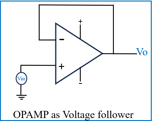
In a voltage follower circuit, the op-amp is connected in a non-inverting configuration. The output is connected directly to the inverting terminal, creating a feedback loop that maintains the output voltage equal to the input voltage.
Here,
Vo = (1+ Rf/Rin)Vin
Vo = (1+ 0) Vin
Vo=Vin
The voltage gain Av is therefore:
Av=Vo/Vin =1
In this way, a voltage follower effectively provides signal isolation and prevents loading effects on the previous stage while maintaining the same voltage level. This makes it an essential component in various applications, such as interfacing between circuits with different impedances.
Conclusion
Operational amplifiers (OPAMPs) are powerful components that play a crucial role in analog electronics. Their ability to perform various mathematical operations — such as addition, subtraction, integration, and differentiation — makes them essential building blocks in signal processing, control systems, and instrumentation. Whether used as summing amplifiers, subtractors, differentiators, integrators, or voltage followers, OPAMPs provide versatility, precision, and reliability. Understanding these fundamental applications allows engineers to design and optimize circuits for a wide range of real-world scenarios, from audio mixers to sensor signal conditioning. Mastering these configurations lays the foundation for more advanced applications in both analog and digital systems.

