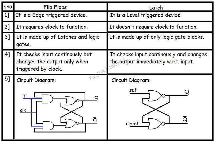
In this blog post, we’ll delve into the implementation of Flip-Flops in Verilog. Flip-Flops are crucial elements in digital circuits, used for storing binary data and synchronizing signals. Understanding how to implement Flip-Flops is fundamental for sequential logic design.
Below are the Verilog codes for different types of Flip-Flops:
1] D Flip-Flop:
module D_FF(input wire clk, input wire reset, input wire d, output reg q);
always @(posedge clk or posedge reset)
begin
if (reset)
q <= 1'b0;
else
q <= d;
end
endmodule
2] JK Flip-Flop:
module JK_FF(input wire clk, input wire reset, input wire j, input wire k, output reg q);
reg q_next;
always @(posedge clk or posedge reset)
begin
if (reset)
q_next <= 1'b0;
else if (j && k)
q_next <= ~q;
else if (j)
q_next <= 1'b1;
else if (k)
q_next <= 1'b0;
end
assign q = q_next;
endmodule
3] SR Flip-Flop:
module SR_FF(input wire clk, input wire reset, input wire s, input wire r, output reg q);
reg q_next;
always @(posedge clk or posedge reset)
begin
if (reset)
q_next <= 1'b0;
else if (s && r)
q_next <= q;
else if (s)
q_next <= 1'b1;
else if (r)
q_next <= 1'b0;
end
assign q = q_next;
endmodule
4] T Flip-Flop:
module T_FF(input wire clk, input wire reset, input wire t, output reg q);
reg q_next;
always @(posedge clk or posedge reset)
begin
if (reset)
q_next <= 1'b0;
else if (t)
q_next <= ~q;
end
assign q = q_next;
endmodule
Explanation:
Each Flip-Flop module has inputs for clock (clk), reset (reset), and specific control signals (d, j, k, s, r, t) depending on the type of Flip-Flop.
The q output represents the stored or computed binary data.
These Flip-Flop modules are synchronized to the positive edge of the clock (posedge clk).
Usage:
Instantiate the desired Flip-Flop module in your Verilog design and connect the input and output wires as needed to implement sequential logic.
The provided Verilog codes for Flip-Flops showcase the implementation of D, JK, SR, and T Flip-Flops, essential for storing and manipulating binary data in digital circuits. Experiment with these codes, understand their behavior, and integrate them into your sequential logic designs.
Happy Coding!!
