or_gate.v
module or_gate(a,b,y);
input a;
input b;
output y;
or(y,a,b);
endmodule
tb_or_gate.v
module tb_or_gate;
reg a;
reg b;
wire y;
or_gate UUT (.a(a), .b(b), .y(y));
initial begin
$display(“Testing OR gate”);
a = 0; b=0;
#10;
$display(“Input_A = %b, Input_B = %b, Output = %b”, a,b,y);
a = 0; b=1;
#10;
$display(“Input_A = %b, Input_B = %b, Output = %b”, a,b,y);
a = 1; b=0;
#10;
$display(“Input_A = %b, Input_B = %b, Output = %b”, a,b,y);
a = 1; b=1;
#10;
$display(“Input_A = %b, Input_B = %b, Output = %b”, a,b,y);
$finish;
end
endmodule
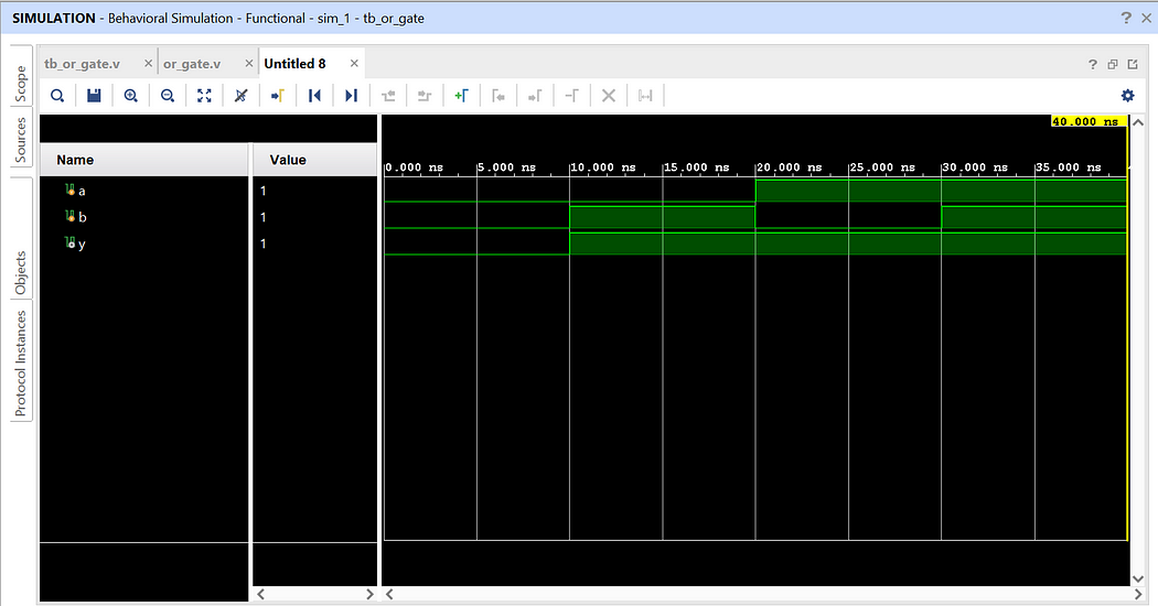
The output waveform for or gate will be as follows:

No comments:
Post a Comment