September 6, 2024

Understanding the Full Subtractor: The Complete Subtraction Solution in Digital Electronics

In digital electronics, subtraction is as essential as addition, particularly when dealing with multi-bit numbers. While the Half Subtractor covers basic single-bit subtraction, it falls short when borrow operations come into play. The Full Subtractor is designed to handle these situations, making it a crucial element in advanced digital systems. This blog post will explore the Full Subtractor, its components, operation, and significance.

What is a Full Subtractor?

A Full Subtractor is a combinational circuit that performs the subtraction of two binary bits while accounting for a borrow from a previous stage. Unlike the Half Subtractor, which handles subtraction without borrow consideration, the Full Subtractor manages both the difference and borrow efficiently in multi-bit binary subtraction. It produces two outputs:

  • Difference (D)
  • Borrow (B_out)

Theoretical Background

Let’s revisit the rules of binary subtraction, adding the case where we borrow from a previous operation:

  • 0–0 = 0
  • 1–0 = 1
  • 1–1 = 0
  • 0–1 = 1 (with a borrow of 1)

When performing multi-bit subtraction, the Full Subtractor must also consider an input borrow (B_in) from the previous less significant bit, leading to more complex calculations.

Components of a Full Subtractor

A Full Subtractor involves three binary inputs:

  • A: The minuend (the number being subtracted from)
  • B: The subtrahend (the number being subtracted)
  • B_in: The borrow input from the previous stage

The Full Subtractor employs the following logic gates:

  • XOR Gates: To compute the difference
  • AND and OR Gates: To compute the borrow output

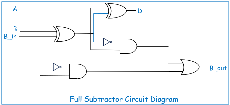
The logic expressions for the outputs are:

  • Difference (D) = A ⊕ B ⊕ B_in
  • Borrow out (B_out) = (A’ ANDB) OR ((A ⊕ B)’ AND B_in)

Circuit Diagram

The Full Subtractor circuit is built using the above components, showing how the XOR gates compute the difference and how the AND/OR gates handle the borrow. Here’s a simplified diagram for better understanding:
Truth Table

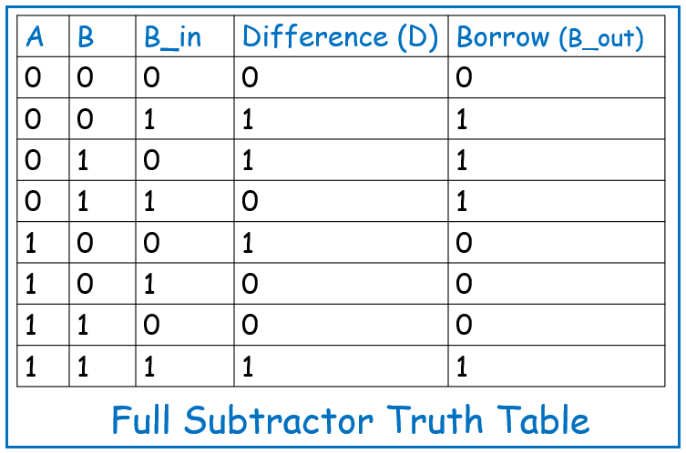
The Full Subtractor truth table details the results of all possible combinations of the three inputs (A, B, and B_in):
Applications of Full Subtractor

The Full Subtractor is vital in systems requiring multi-bit subtraction, including:

  • Arithmetic Logic Units (ALUs): A core component in CPUs for handling multi-bit arithmetic operations.
  • Digital Counters: Used in applications that require down-counting, where the Full Subtractor helps manage borrow operations.
  • Binary Calculators: Necessary for performing precise binary arithmetic.
  • Data Processing Systems: In systems requiring complex binary operations, the Full Subtractor plays a key role in ensuring accurate computations.

Conclusion

The Full Subtractor extends the functionality of the Half Subtractor by accounting for borrow operations, making it indispensable in multi-bit subtraction scenarios. Understanding the Full Subtractor’s logic and applications is essential for advancing in digital circuit design and gaining a deeper insight into how subtraction is handled in various digital systems. As you move toward more complex circuits, mastering the Full Subtractor will provide a strong foundation for future exploration in digital electronics.
September 5, 2024

Mastering Verilog: Implementing a Barrel Shifter

Welcome to another edition of our Verilog series! In this blog post, we’ll explore the implementation of a Barrel Shifter in Verilog. A Barrel Shifter is a versatile digital circuit used for shifting data bits left or right by a specified number of positions. It’s a fundamental building block in many digital systems, particularly in arithmetic operations and data manipulation.

Below is the Verilog code for a Barrel Shifter, implemented using a Behavioral Modeling approach:

In the behavioral modeling approach, we describe the shifting functionality using simple conditional logic to decide between left and right shifts.

module barrel_shifter(
output reg [7:0] out, // Output shifted result
input [7:0] in, // Input data
input [2:0] n, // Number of positions to shift
input l_r // Shift direction (1 for left, 0 for right)
);
always @(*) begin
if (l_r) begin
// Left shift operation
out = in << n;
end else begin
// Right shift operation
out = in >> n;
end
end
endmodule

Explanation:

  • The always@(*) block ensures that the ‘out’ signal is updated whenever there is a change in the inputs ‘in’, ‘n’, or ‘l_r’.
  • If ‘l_r’ is high (‘1’), the input ‘in’ is shifted left by ‘n’ positions using the ‘<<’ operator.
  • If ‘l_r’ is low (‘0’), the input ‘in’ is shifted right by ‘n’ positions using the ‘>>’ operator.

Conclusion

This Verilog implementation of a Barrel Shifter demonstrates how to model a data-shifting circuit using behavioral constructs. Understanding how to design and implement a Barrel Shifter is essential for various applications in digital design, including arithmetic operations and data manipulation.

What’s Next?

Experiment with this Barrel Shifter design in your Verilog projects and explore how shifting data can be applied to solve different problems. In the next post, we’ll delve into more advanced digital circuit designs and their Verilog implementations.

Happy Coding!

Understanding Encoders: Translating Inputs to Binary Code in Digital Systems

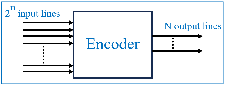
In digital electronics, an encoder is a crucial combinational circuit used to convert multiple input signals into a smaller, coded binary output. Encoders are widely used in digital systems for the efficient conversion of parallel inputs into serial binary codes, making them vital in devices like keyboards, control systems, and more.

What is an Encoder?

An encoder is a combinational circuit that converts multiple input signals into a coded output, typically in binary form. Encoders simplify complex data by reducing the number of signals needed to represent information. In essence, they perform the opposite function of decoders, which take a binary code and convert it into a specific output.

A basic encoder takes 2^n inputs and provides an n-bit binary output. This feature makes encoders extremely useful in applications where data reduction or compact representation is necessary.

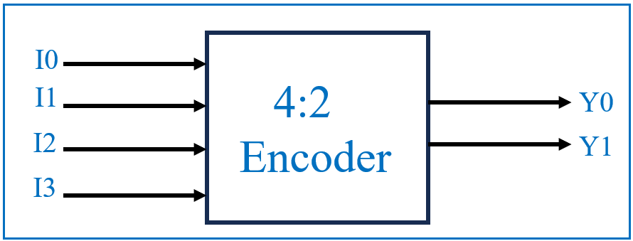
For example, a 4-to-2 encoder has four input lines (I0, I1, I2, I3) and two output lines (Y0, Y1). It takes the active input and converts it into a corresponding 2-bit binary code.

Types of Encoders

Encoders can be classified into different types based on their design and specific applications. Some of the most common types include:

  • Binary Encoder: Converts 2^n input lines into n output lines, where each input is represented by a unique binary code. For example, a 4:2 encoder has four inputs and two outputs, encoding one active input into its binary equivalent.
  • Priority Encoder: Adds functionality by assigning a priority to each input line. If more than one input is active at the same time, the encoder will prioritize the highest-order input and encode it. This type of encoder is useful when handling multiple simultaneous signals.
  • Octal-to-Binary Encoder: Converts 8 input lines into a 3-bit binary output. It is typically used in systems where there are eight possible input states that need to be encoded into binary form for further processing.
  • Decimal-to-BCD Encoder: Converts decimal input values into Binary-Coded Decimal (BCD). It’s widely used in calculators and other digital systems that need to display numbers as decimal digits, but process them as binary internally.

4:2 Encoder Explained

The 4:2 encoder consists of four inputs and two outputs. Only one input can be active at a time to generate the respective binary code at the output. The following truth table and logic diagram will illustrate the functionality.

This diagram represents a simple 4:2 encoder, which consists of four inputs (I0, I1, I2, and I3) and two outputs (Y0, Y1). The role of this encoder is to take one active input from the four inputs and convert it into a 2-bit binary output. The truth table provides a clear representation of the relationship between the inputs (I0, I1, I2, I3) and the outputs (Y0, Y1). The encoder works by mapping each input to a unique binary code based on the active input.

4:2 Encoder Logic Using OR Gates
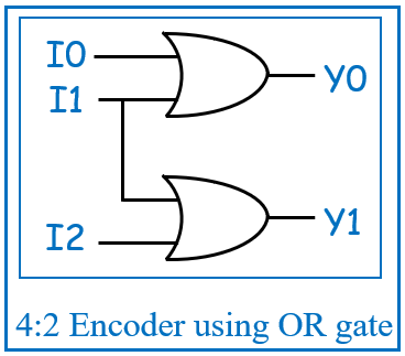
The logic diagram for a 4:2 encoder can be implemented using OR gates. In this diagram, the inputs are combined logically to produce the binary output. The Boolean equations that define the behavior of this encoder are:

  • Y0 = I1 OR I3
  • Y1 = I2 OR I3

These expressions show how the two OR gates combine the inputs to generate the respective outputs. If the inputs I1 or I3 are high, Y0 will be 1. Similarly, if I2 or I3 are high, Y1 will be 1. This ensures that the encoder produces the correct binary representation for each input.

Applications of Encoders

Encoders are widely used in various digital systems where data compression and signal reduction are needed. Some common applications include:

  1. Keyboards: Each key on a keyboard generates a unique binary code through an encoder, allowing the system to interpret the input efficiently.
  2. Control Systems: Encoders are used in control systems to encode signals for easy processing and transmission.
  3. Robotics: Encoders help track and control motion in robotic systems by encoding position or velocity data into a digital format.
  4. Multiplexers: Encoders are often used in multiplexing systems to select data channels for transmission.

Verilog Code for 4-to-2 Encoder

Here’s a simple Verilog code for a 4-to-2 binary encoder:

module encoder(y, v, i);
input [3:0] i; // 4-bit input
output reg [1:0] y; // 2-bit output
output reg v; // Valid output
always @(*) begin
case(i)
4'd1: {v, y} = 3'b100; // Input 1 maps to output 00
4'd2: {v, y} = 3'b101; // Input 2 maps to output 01
4'd4: {v, y} = 3'b110; // Input 4 maps to output 10
4'd8: {v, y} = 3'b111; // Input 8 maps to output 11
4'd0, 4'd3, 4'd5, 4'd6, 4'd7, 4'd9, 4'd10, 4'd11, 4'd12, 4'd13, 4'd14, 4'd15: {v, y} = 3'b000; // All other cases
default: $display("error"); // Display an error message for undefined cases
endcase
end
endmodule

Conclusion

Encoders are vital in digital electronics for converting multiple inputs into simplified binary outputs. Their ability to reduce data and prioritize signals makes them essential in many systems, including control systems, multiplexers, and more. Understanding how encoders work and how to implement them in hardware description languages like Verilog will strengthen your knowledge of digital circuit design.

Mastering Verilog: Implementing a 4-to-2 Encoder

Welcome back to our Verilog series! In this blog post, we’ll dive into the implementation of a 4-to-2 Encoder in Verilog. Encoders are essential digital components that convert multiple input lines into fewer output lines, simplifying data representation in digital circuits.

Below are the Verilog codes for a 4-to-2 encoder using two different modeling styles: Dataflow and Behavioral.

1] Dataflow Modeling:

In dataflow modeling, we use continuous assignments to describe the functionality of the encoder. Here’s the Verilog code:

module encoder(y, v, i);
input [3:0] i; // 4-bit input
output [1:0] y; // 2-bit output
output v; // Valid output
assign y = {i[3] | i[2], i[3] | i[1]}; // Encode the input
assign v = |i; // Valid output if any input is high
endmodule

Explanation:

  • ‘assign y = {i[3] | i[2], i[3] | i[1]};’ uses bitwise OR operations to determine the output based on the highest active input.
  • ‘assign v = |i;’ sets the valid output high if any input bit is set.

2] Behavioral Modeling:

In behavioral modeling, we use an ‘always’ block to describe the encoder’s functionality with a ‘case’ statement. Here’s the Verilog code:

module encoder(y, v, i);
input [3:0] i; // 4-bit input
output reg [1:0] y; // 2-bit output
output reg v; // Valid output
always @(*) begin
case(i)
4'd1: {v, y} = 3'b100; // Input 1 maps to output 00
4'd2: {v, y} = 3'b101; // Input 2 maps to output 01
4'd4: {v, y} = 3'b110; // Input 4 maps to output 10
4'd8: {v, y} = 3'b111; // Input 8 maps to output 11
4'd0, 4'd3, 4'd5, 4'd6, 4'd7, 4'd9, 4'd10, 4'd11, 4'd12, 4'd13, 4'd14, 4'd15: {v, y} = 3'b000; // All other cases
default: $display("error"); // Display an error message for undefined cases
endcase
end
endmodule

Explanation:

  • The always@(*) block ensures that ‘y’ and ‘v’ are updated based on changes in ‘i’.
  • The ‘case’ statement maps specific input values to their corresponding output values.
  • The ‘default’ case displays an error message for undefined inputs.

Conclusion

These Verilog implementations showcase how to model a 4-to-2 Encoder using different design approaches: dataflow and behavioral. Understanding these modeling styles will help you design and implement encoders effectively in your digital circuits.

What’s Next?

Experiment with these encoder implementations in your Verilog projects and explore variations to deepen your understanding. In the next post, we’ll explore more complex digital circuits and their Verilog implementations.

Happy Coding!

Mastering Verilog: Implementing a 3-to-8 Decoder

Welcome to another post in our Verilog series! In this edition, we will explore the implementation of a 3-to-8 Decoder in Verilog. A decoder is a combinational circuit that converts binary information from ‘n’ input lines to a maximum of 2^n unique output lines.

3-to-8 Decoder takes a 3-bit binary input and decodes it into one of eight outputs. This is a fundamental building block in digital circuits used for tasks like address decoding and data routing.

Below are the Verilog codes for a 3-to-8 decoder using two different modeling styles: Dataflow and Behavioral.

1] Dataflow Modeling:

In dataflow modeling, we use bitwise operations and concatenation to describe the decoder’s functionality succinctly.

module decoder_3_8(y, i, en);
input [2:0] i; // 3-bit input vector
input en; // Enable signal
output [7:0] y; // 8-bit output vector
assign y = {en & i[2] & i[1] & i[0],
en & i[2] & i[1] & ~i[0],
en & i[2] & ~i[1] & i[0],
en & i[2] & ~i[1] & ~i[0],
en & ~i[2] & i[1] & i[0],
en & ~i[2] & i[1] & ~i[0],
en & ~i[2] & ~i[1] & i[0],
en & ~i[2] & ~i[1] & ~i[0]};
endmodule

Explanation:
‘assign y = { … };’ constructs an 8-bit output where each bit is set based on the combination of input bits and the enable signal. Each bit of ‘y’ represents one of the 8 possible states defined by the 3-bit input ‘i’ and the enable signal ‘en’.

2] Behavioral Modeling:

In behavioral modeling, we describe the decoder’s functionality using a ‘case’ statement to handle all possible input combinations.

module decoder_3_8(y, i, en);
input [2:0] i; // 3-bit input vector
input en; // Enable signal
output reg [7:0] y; // 8-bit output vector
always @(*) begin
case ({en, i})
4'b1000: y = 8'b00000001;
4'b1001: y = 8'b00000010;
4'b1010: y = 8'b00000100;
4'b1011: y = 8'b00001000;
4'b1100: y = 8'b00010000;
4'b1101: y = 8'b00100000;
4'b1110: y = 8'b01000000;
4'b1111: y = 8'b10000000;
default: y = 8'b00000000; // Error handling
endcase
end
endmodule

Explanation:
The always@(*) block updates the output y based on the combination of the enable signal ‘en’ and the input ‘i’. The ‘case’ statement ensures that the correct output line is activated for each possible input combination.

Conclusion

These Verilog implementations demonstrate how to model a 3-to-8 Decoder using different design approaches: dataflow and behavioral. Understanding these methods will help you design and implement decoders efficiently in your digital systems.

What’s Next?

Experiment with these decoder implementations in your Verilog projects and explore their applications in complex digital circuits. Stay tuned for more posts on digital design and Verilog coding!

Happy Coding!

Explore Our Topics!

Check out the extensive list of topics we discuss:  Tech and AI Blogs Communication Protocols: -  USB   - RS232   -  Ethernet   -  AMBA Prot...